Distributor Rebuild
As a result of the coil dying on the way home from the Monterey trip, I decided to pull the distributors and have them rebuilt. When I rebuilt the engine back in 1982, I just replaced the points, gapped them with a feeler gauge and timed them opposite each other with a light. This was 'good enough for government work', but after driving Lowell Brown's 330, mine wasn't nearly as smooth. Plus replacing the bad coil with the distributor on the car would be quite difficult.
Lowell had his distributors rebuilt by Carlo Durante (Alfa of Tacoma) with excellent results, so I decided to do the same.
I rotated the engine to leave it at top dead center on cylinder 1. Then I took pictures of both distributors so I knew which spline to use when I re-installed them.
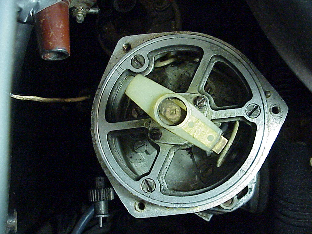
Removing the distributors is very time consuming as access to the bolts and nuts is very limited. However, about 2 hours later, I had both in hand. The LH distributor is very difficult to remove by itself. I found that removing the RH one first allows one to reach across the back of the engine and have better access to the LH fasteners. You may also have to loosen the LH distributor adjustment nuts to rotate the top for enough clearance to clear the studs and spline.
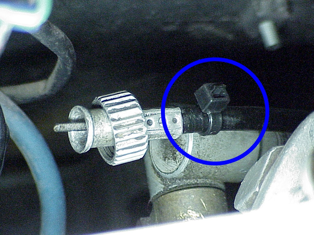
Another trick I've found useful is to put a plastic wire tie on the tachometer cable to prevent the nut from sliding down the cable out of reach. This is also handy on the tach and speedometer cable ends under the dash.
After Carlo was done with the rebuilds, the curve looks like this:
Carlo said that it looked like these distributors had never been apart. He replaced the worn parts and cleaned everything so the advance weights worked smoothly and evenly. The Nominal line is from the 330 GT Service Manual and has a ±1° tolerance. So mine are within specifications. The other reason to have the distributors set using a distributor machine is to get the dual points in each set properly. You can't measure the dwell angle with the distributors on the car nor can you set the point gap very accurately due to the limited working space. Once the point gap is set properly for each set of points, then you have to get them opening exactly 180° to each other. Unlike dual points the Mallory distributor system where they are used to lengthen the dwell angle, the ones in the V-12s independently fire three cylinders each. The distributor has a three lobed cam. So one set of points fires three cylinders in one distributor revolution while the other fires the other three. If both sets of points are not exactly at 180° to each other, three of the cylinders will be out of time. This setting is much easier done on a distributor machine than trying to do it on the car.
Since Carlo had done most the distributor point synchronization, I just just started with the last two paragraphs and followed with the distributor timing.
Here's some information from the FAF Ferrari Tuning Tips
and Maintenance Techniques book (now in reprint from
VelocePress):
DISTRIBUTOR POINT SYNCHRONIZATION
This tip comes from Dudley Kuhlman of Columbus, OH:
In order to do an accurate job of point synchronization, you need to make yourself distributor holder so you can take the distributor out of’ the car and have it on the bench, mounted solid so there is no rocking, but where you are still able to turn the bottom of the shaft. You will also need a degree wheel, a pointer, and a self-powered timing light.
The degree wheel can be made from one of the smaller types used for crankshafts. They are usually 6, 7 or 8 inches in diameter, and can often be bought in a good Hot Rod shop. Then have someone with a lathe cut the inside out so it just fits over the distributor with the cap off, and put in a centering pin hole so the degree wheel can't turn.
The pointer must fit well on the distributor shaft, and can be the spring-over type. It should he long enough to reach out to the edge of the degree wheel. It will be more accurately read if it has a right angle end.
The timing light should be the flashlight type with two wires which plug into the base. McCullough dealers are one possible source for the required type of light.
The procedure is thus: Set the point gap on both sets of points (.014 in), put the degree wheel in place, attach the pointer, and hook one lead from the lining right to the high voltage outlet on the side of the distributor, and the other lead to the ground.
Turn the shaft until the light goes on (or off, depending upon which way you want to do it, but once you pick one, remain constant). Continue to turn the shaft, seeing if the light goes on (or off) every sixty degrees. If not, some adjusting is in order.
Depending upon what kind of reading you are getting, it may be necessary to move one or both sets of points. This can be done easily enough without disturbing the original point gap setting. Once you have the new position secure, check it again with the light and degree wheel. It takes time and patience to get it right, but it is possible to come out with it set up so you have the points synchronized at sixty degrees all the way around.
Once the distributor is set up on the bench, go back to the car, bring the 10AF mark on the flywheel for the bank you are working with into line with the fixed pointer, put the distributor back on, and with the same timing light hooked up to the high voltage lead, rotate the distributor body until the light just comes on (goes off). Secure the nuts holding the body and you should be "On Time". Repeat for the other distributor.
Finally, check the timing with the engine running [per the following].
To completely time a late model V-12 Ferrari, follow these procedures:
REQUIRED MATERIALS:
Electronic strobe timing light
14 mm wrench
.014 in (.35 mm) feeler gauge
PREREQUISITES:
Before attempting to time your Ferrari, Be sure these conditions are present:
Points should be new or, old, in good condition. File old points with an ignition point file so that a smooth parallel surface remains.
Point gaps should be checked and set to the recommended .014 in.
PROCEDURES:
- Remove the inspection plate on top of the bellhousing.
NOTE: To avoid removing the cover plate on the bellhousing, substitute clear plastic (preferably an unbreakable Lexan
one) plate for the metal plate. - Make sure the markings on the flywheel are readable. If necessary, clean
them with solvent.
RIGHT BANK:
- Connect an electronic strobe timing light to cylinder no. 1 (on the right bank).
- Start the engine and allow it to idle below 1000 rpm.
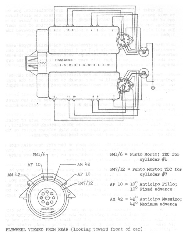
- Aim the timing light into the inspection port above the flywheel. The 10AF mark which is just before the PM1/6 mark on the flywheel should be near the fixed pointer.
- Increase the engine speed to 5000 rpm. The 42AM mark which is 42° before the PM1/6 mark on the flywheel should be near the fixed pointer.
- If the 42AM does not line up with the pointer, loosen the all nuts
holding the distributor top to the base just enough to allow the distributor
top to be moved. Rotate the distributor top until the 42AM lines up with the
pointer. Retighten the 14 mm nuts.
NOTE: It is more important that the timing be correct at high speed than at idle speed. Therefore, if the 42AM lines up, and the 10AF is within 2° of lining up, that is good enough. If the discrepancy is more than this, check the advance mechanism in the distributor base and all the distributor bearings for wear.
- Stop the engine and connect the timing light to cylinder no. 6 (on the right bank).
- Start the engine and increase its speed to 5000 rpm. The same 42AM mark (now 360° later) should be near the fixed pointer.
- If the 42AM does not line up with the pointer, stop the engine and
adjust the position of the second "even cylinder" set of points by loosening
the two screws and sliding the set forward or backward, thereby timing the
even numbered cylinders.
NOTE: To determine which points control the even and the odd numbered cylinders, turn the engine over until the rotor points to
no. 1 on the distributor cap. The set of points that are just opening are the odd numbered set (the flywheel should be just coming up to the 10AF mark also). This “odd set" is not adjusted for timing purposes, only the "even set" is moved to adjust the cylinder no. 6 firing position.
- This completes the timing of the right cylinder bank. Be sure to check
the tightness of the 14 mm distributor nuts and the point screws.
LEFT BANK:
- Connect the timing light to cylinder no. 7 (on the left bank).
- Start the engine and allow it to idle below 1000 rpm.
- Aim the timing light into the inspection port above the flywheel. The 10AF mark which is just before the PM7/12 mark on the flywheel should be near the fixed pointer.
- Increase the engine speed to 5000 rpm. The 42AM mark which is 42° before the PM/12 mark on the flywheel should be near the fixed pointer.
- If the 42AM does not line up with the pointer, loosen the 14 mm nuts
holding the distributor top to the base just enough to allow the distributor
top to be moved. Rotate the distributor top until the 42AM lines up with the
pointer. Retighten the 14 mm nuts.
NOTE: Again, it is more important that the timing be correct at high speed than at idle speed.
- Stop the engine and connect the timing light to cylinder no. 12 (on the left bank).
- Start the engine and increase its speed to 5000 rpm. The same 42AM mark (now 360° later) should be near the fixed pointer.
- If the 42AM does not line up with the pointer, stop the engine and
adjust the position of the second “even cylinder” set of points by loosening
the two screws. arid sliding the set forward or backward, thereby timing the
even numbered cylinders
NOTE: To determine which points control the even and the odd numbered cylinders, follow the directions in the note under step no. 10 above, using cylinder no. 7 rather than cylinder no. 1.
- This completes the timing of the left cylinder bank. Be sure to check the tightness of the 14 mm distributor nuts and the point screws.
- It is always wise to repeat the distributor timing check after adjusting the timing to double check your accuracy.