Front Brakes
The drive in Canada really made me realize that I needed to address the front brakes. The car would pull to the left upon light braking and then to the right when heavier braking was done. This made it quite interesting getting set up to take a curve using trail braking. You were never quite sure where the car would be with respect to the line, so I would have to brake early, get everything set with regard to braking and then get back on the right line for the curve.
Since everything is apart on the front suspension now, I'm taking the time to work on the brakes as the car is already on the lift for a while. I took off the brakes and sent them off to White Post Restorations to have them re-sleeved in brass, new pistons, new stainless steel cross-over pipes, etc. They came back a couple of days ago and look really nice.

I also took off the hubs to have the rotors lightly turned. A couple of things I found out. It is easier to drill through the cotter pin using the center hole in the spindle than trying to remove the cotter pin in one piece with the limited space. Once done, the remains can be removed from both sides easily. A 7/64" drill bit just fit into the spindle hole. The nuts holding the hubs to the spindles are LH thread on the left side and RH on the right side, just like the knock-offs.
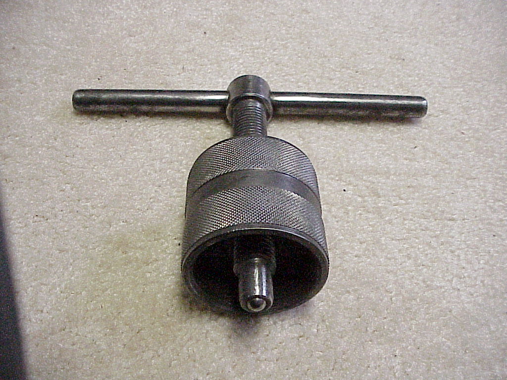
I actually used the hub puller from my toolkit. I had never thought about why the hub puller had threads on both sides. The threads for the knock-offs are different on each side of the car. This tends to make the knock-offs tighten when the car is moving forward rather than tighten on one side and loosen on the other. So the hub puller also has to have right and left hand threads. So when moving to the other side of the car, you have to unscrew the T-handle and screw in it from the opposite side.
After removing the hubs, I found that one of the outer bearings had been replaced with a non-standard one. I was happy that it was an outer bearing since they are only tens of dollars rather than the hundreds that the inner ones are. This hub also had a couple of thousandths of end play that I hope will be remedied with the new bearing. Removal of the bearings is interesting.
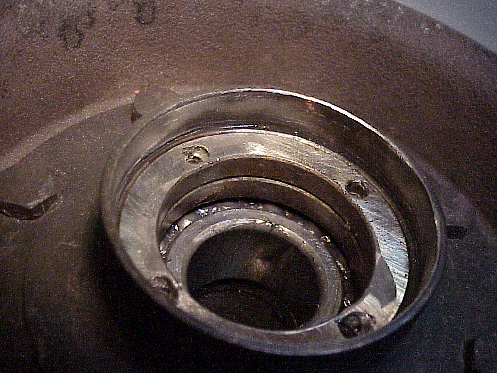
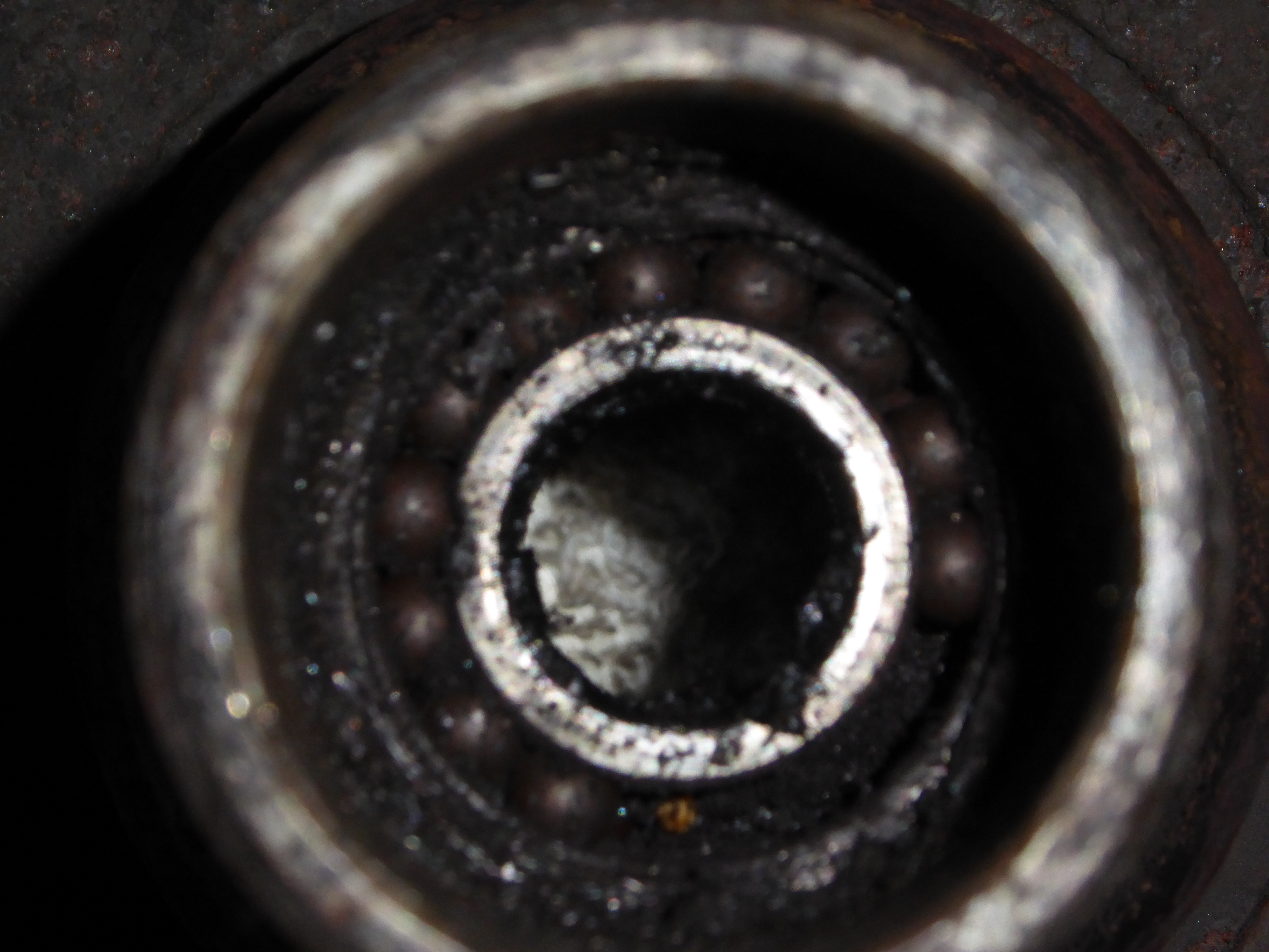
The parts 7 and 8 are locking rings that hold the inner bearing (6) in place. Part 7 is right hand thread and locks the inner bearing. Part 8 is left hand thread and acts like a lock nut for part 7. The real problem is that removal and installation require a special tool that has 4 pins at the end that fit into 4 holes in each locking ring. The machine shop I took the hubs to does quite a bit of work on Ferraris, so they had made this tool for some previous job. The outer bearing (2) is held in place by a C-ring (4). Here you can see the holes and the two locking rings with the inner bearing below them.
So I've got a new outer bearing on the way, but until it arrives, not much else can be done.
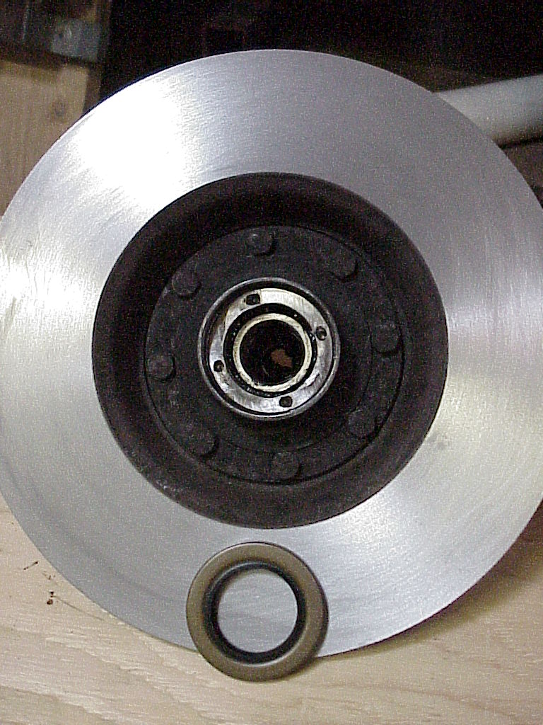
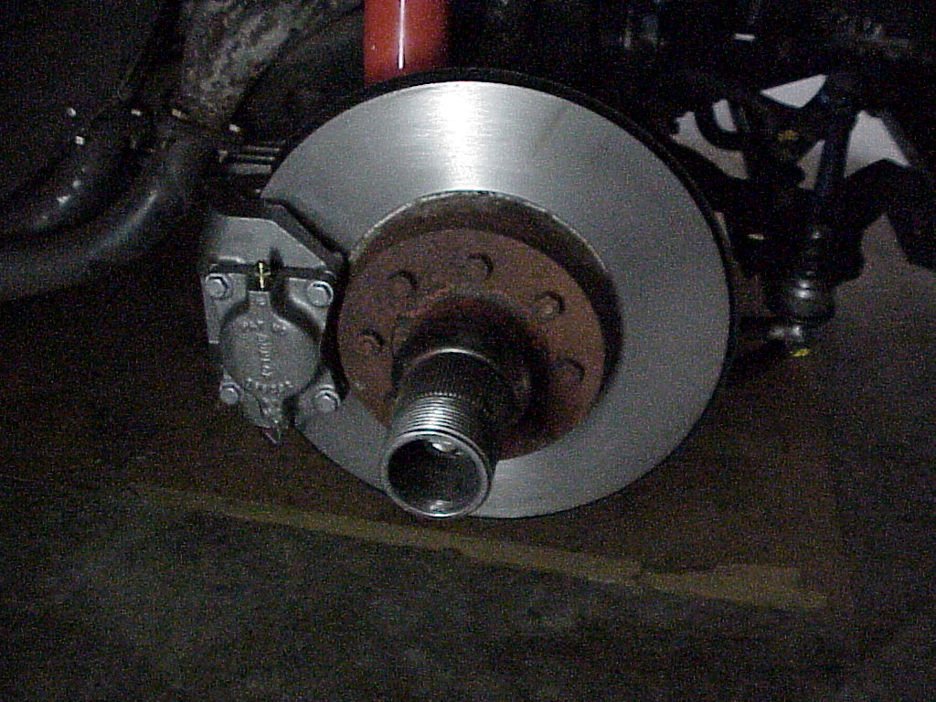
It turns out that the non-standard bearing is the type that is now available. So I ended up keeping the original bearing and returning the new one (which was the wrong one anyway). The machine shop adjusted the end play by changing the shim (part 3) inside the hub. Here's one of the machined rotors and the new seal ready to be installed.
One of the last things in having the rotors machined is to calculate the proper shims so the rotors are centered between the calipers. The shims are part 12 in the diagram above and fit between the brake assembly and the backing plate.
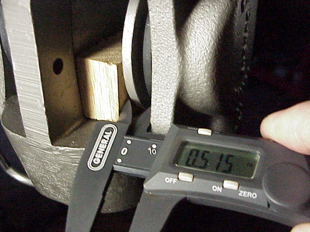
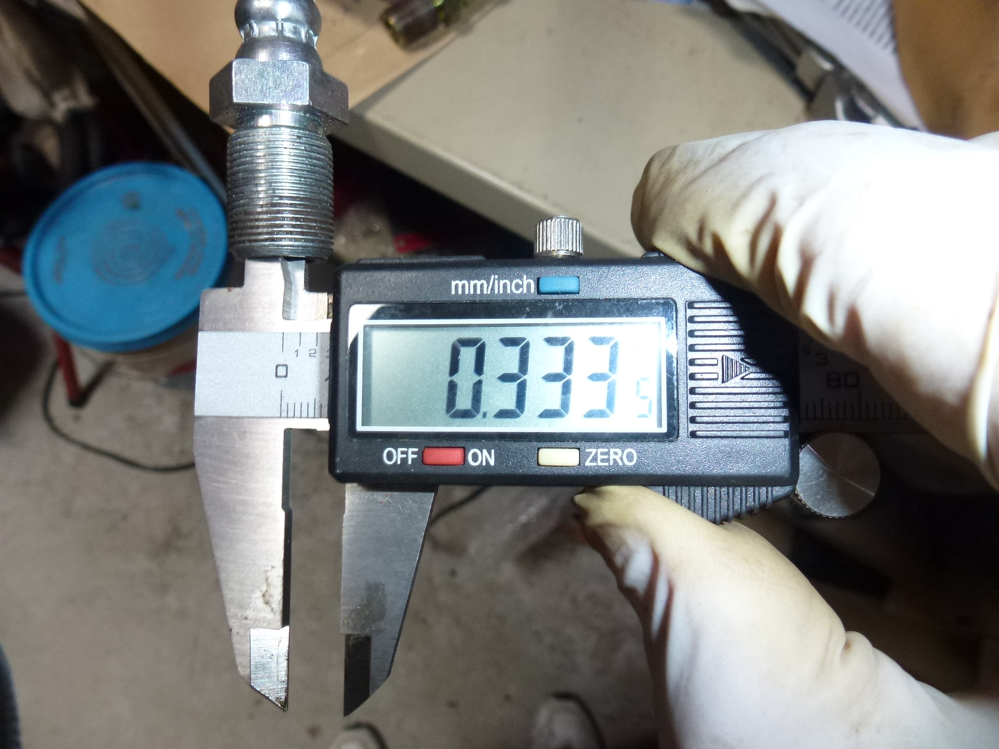
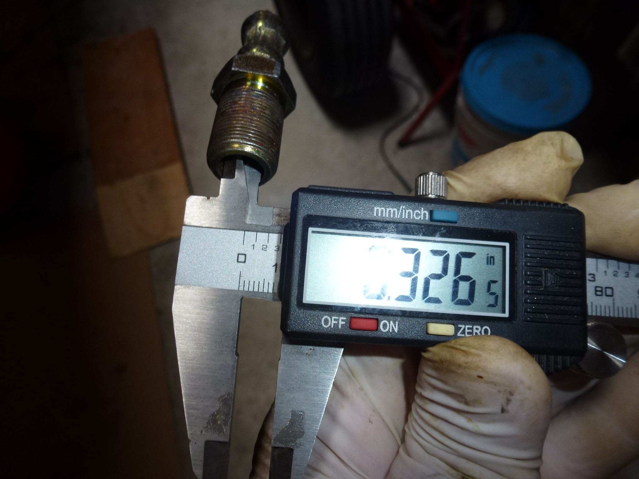
One side is .547". The other side is .517". So I need shims of .015" which will leave a distance of .532" on each side. As the shims don't seem to be available, I'll just order some shim stock and make them. They are just thin washers with an outside diameter of 1" and an inside hole of 1/2". They should be pretty easy to do. I need to do the same measurements on the left brake as the distances probably won't be the same. Each time a rotor is ground, the distances change depending on how much material is taken off each side of the rotor.
Making the shims for the brakes is not as easy as I thought it would be. I'm using a 1 1/8" hole saw (inner diameter of 1") to cut the outside and a regular 1/2" drill bit for the inner hole. It's hard to get both the 1" and 1/2" holes in line with each other. I've done a dozen or so using my drill press, but only satisfied with 2. The problem is that my drill press has too much wobble in the spindle. I ended up going back to my neighbor Mike's shop and using his big drill press. It has a 3/4" spindle, so no wobble. Here is a shim that needs cleanup on the left and a completed one on the right.
![]()
| Side | Original dimension | Shim | Final Dimension |
| Left Outside | .697" | .010" | .687" |
| Left Inside | .679" | .010" | .690" |
| Right Outside | .709" | .015" | .693" |
| Right Inside | .673" | .015" | .688" |
The front brakes are now centered with new brake pads, ready to be bled. I'll bleed them after I replace the clutch slave cylinder as that will need to be bled too.
After all of that, the front brakes still pulled some. Further, the right front dragged some. I talked to White Post and they said to send that brake back and they would take a look at it at no charge. However they thought it was probably the brake hose having a collapsed interior. The brake fluid would push out under the brake pedal pressure, but would be slow to flow back, preventing the brake from retracting properly. I ordered a new brake hose and installed it at the same time. That cured the dragging, but the car still pulled a little on braking. I figured that if one hose was collapsed, the other couldn't be far behind and perhaps was preventing the fluid from flowing to the left brake as easily as the right. So I got another brake hose and installed it too.
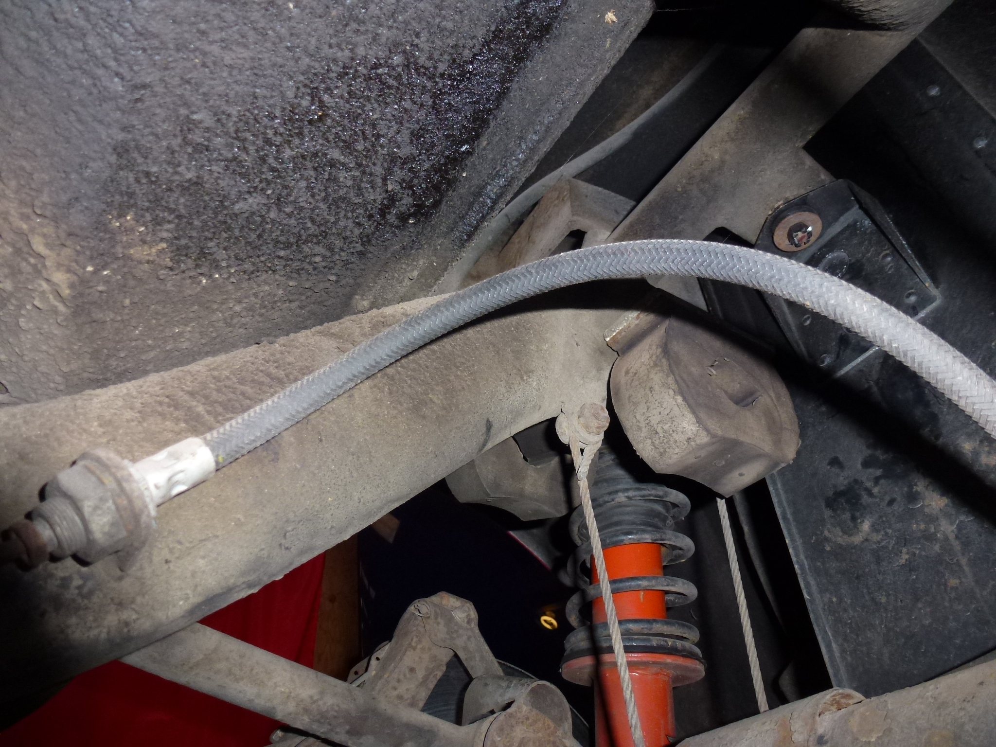
It seems only yesterday that I replaced the front hoses, however, it has been 9 years. The other day, I went to a local cars and coffee show and on the way home, the left front was dragging. By the time I got home, lots of smoke and heat from under that fender.
So I ordered new brake hoses, three this time so I could replace the single one in the rear too. I started with the left front since it was the one with the problem. Taking the old hose off wasn't too bad as I just cut it right at each fitting. This lets one use long sockets to unscrew the fittings easily. The hose screws into the caliper and then the other end is fit through a bracket, tightened with a lock washer and nut. Then the flare nut is screwed back into the new hose fitting.
Sounds easy, and I thought that the whole thing would take an hour or so, including bleeding. Not to be of course. I could not get the flare nut to screw into the new hose. The location is tight and it is difficult to get the flare nut aligned with the hose fitting and get the threads started. One needs to be very careful, if you cross thread the nut and mess up the threads, you are toast as you probably have to pull the engine to replace the hard brake line to get a new flare nut on the end. Anyway, the flare nut did not want to thread in correctly. I kept futzing with it and had no success. I finally unscrewed the end from the caliper, figuring that I would have more control by being able to spin the hose fitting too. If this worked, I would remove the caliper, spin it onto the far end and remount it. Even that didn't work. I just could not get the flare nut to screw into the new hose fitting. I finally gave up for the day as I was frustrated, tired and that's a good way to have things get worse.
Another day, so I decided to do the rear brake line first. It is a lot more accessible and I hoped to at least make some progress toward getting the whole project done.
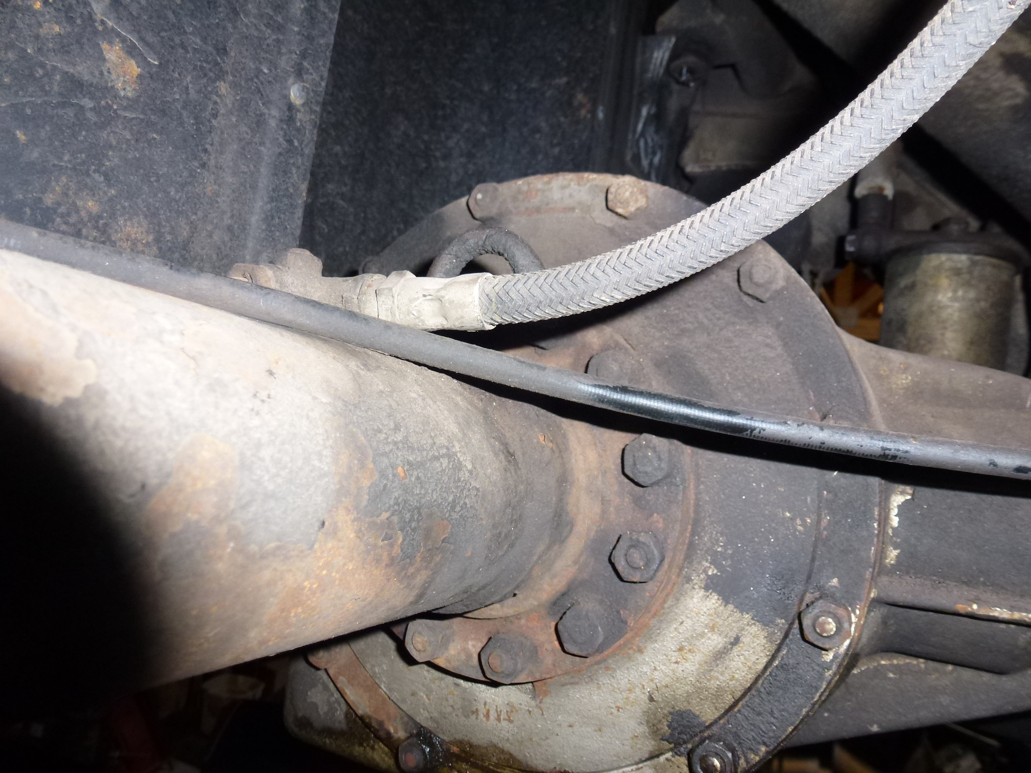
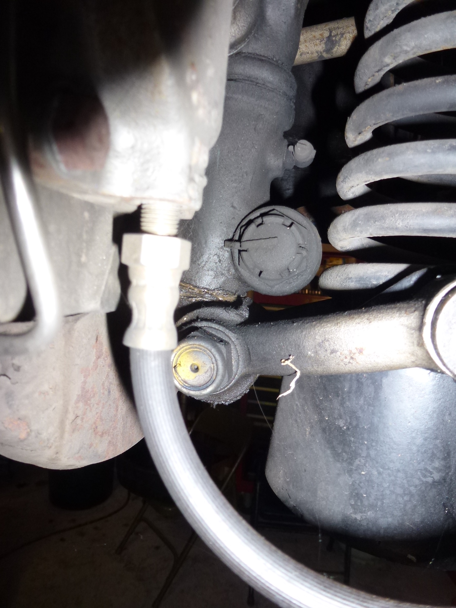
Removing the old hose was just as easy. However, when I unscrewed the far end from the T fitting on the differential, I noticed that the fittings were different between the old and new hoses. As you can see, the old hose was a short square end while the new one had a long tapered end. Ferrari specifies the same part number for both the front hoses and this rear one. The front calipers do have a tapered bottom, but the T fitting does not. So I ended up cutting off part of the new fitting, squaring it up, chamfering the hole and using a copper washer just like the old hose had.
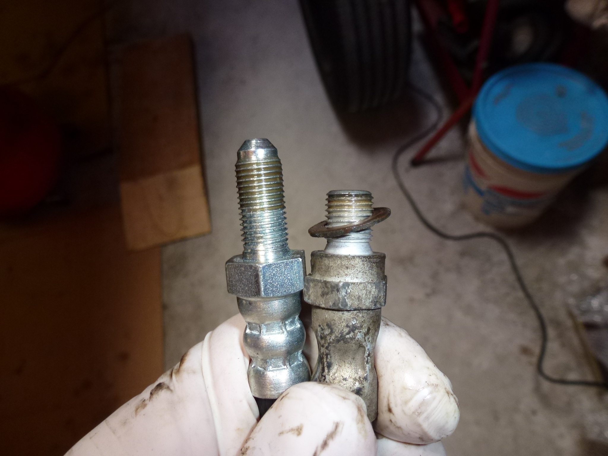
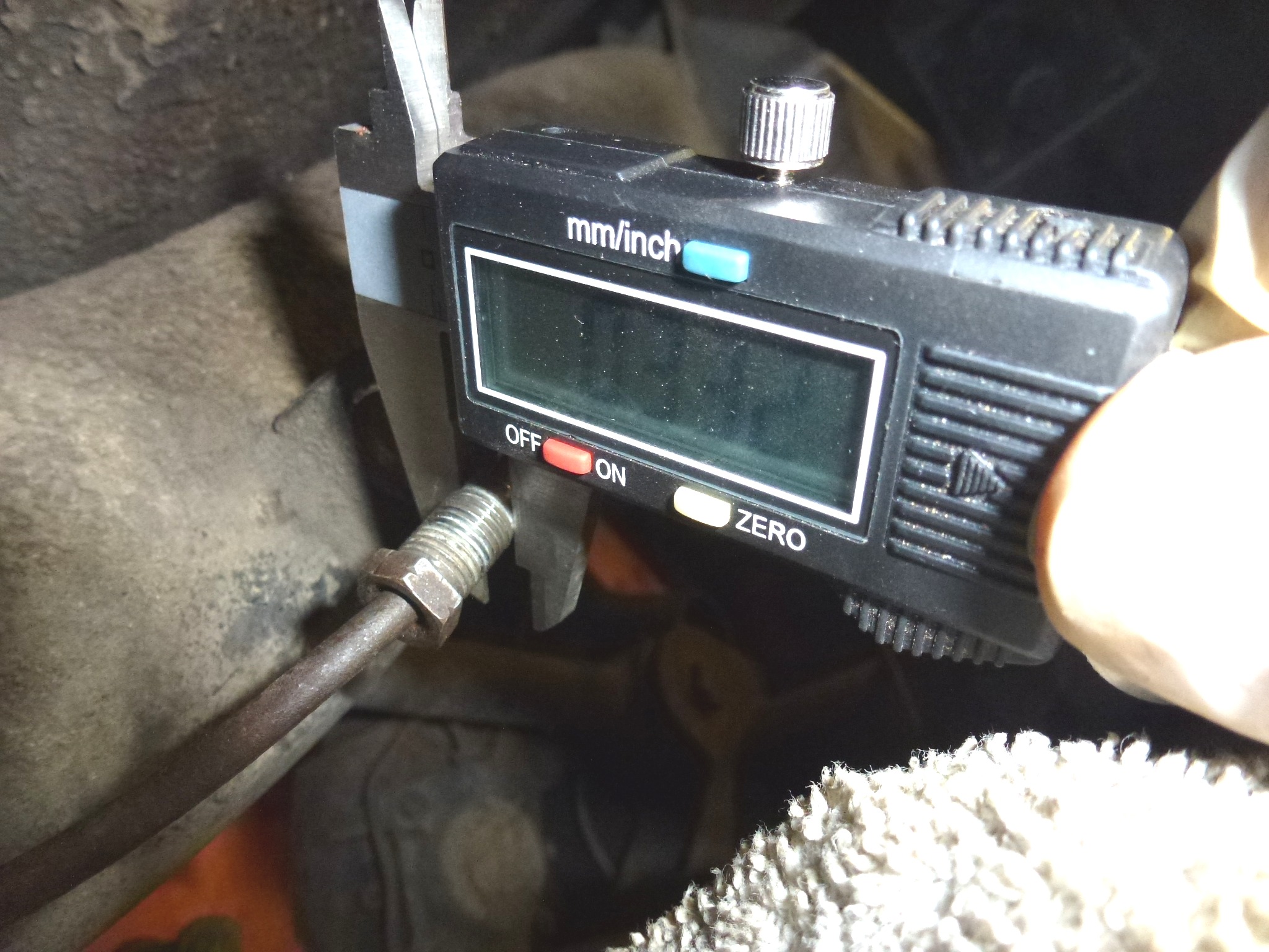
Then it was time to screw the flare nut into the new hose. I had the same problem as in the front, the threads just wouldn't start. However, now with the better access and visibility, I was able to see what the problem was. The old hose fitting would screw right on while the new one would not. It turns out that the new hose interior threads were slightly (a few thousands) narrower that the old hose fitting.
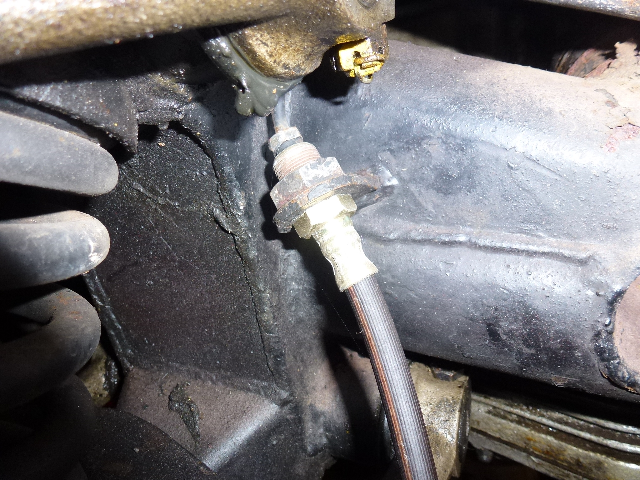
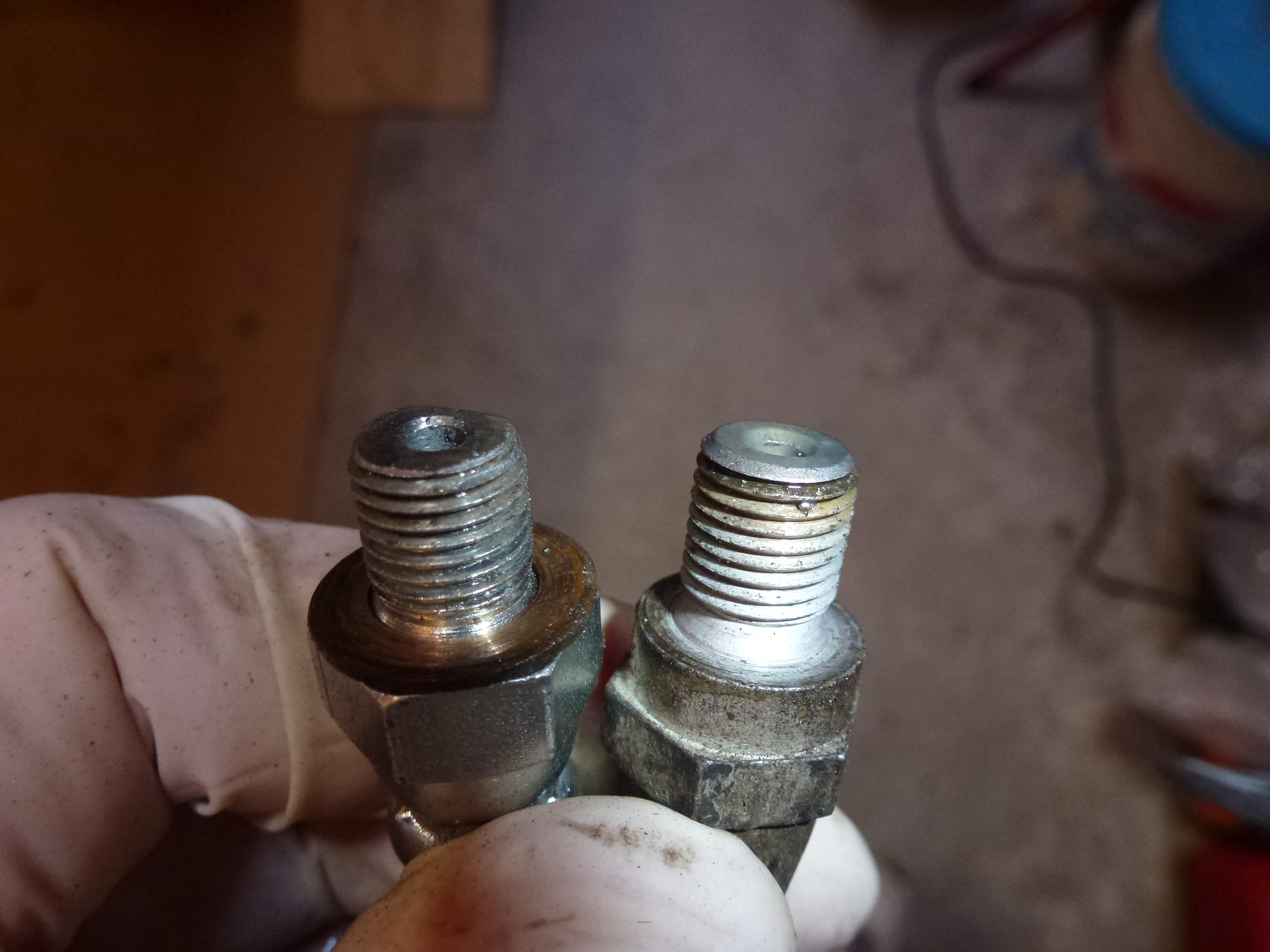
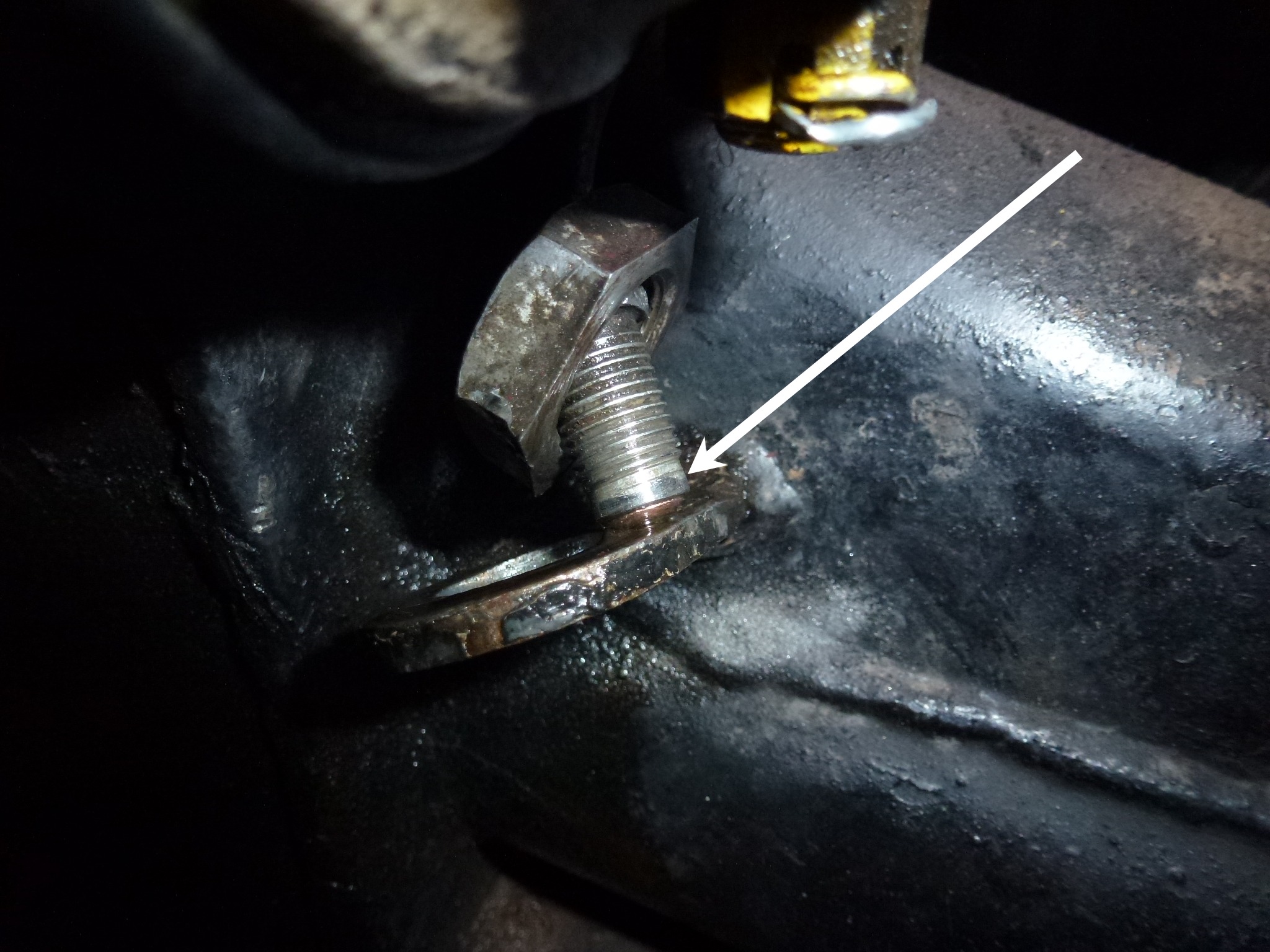
The unthreaded neck (see white arrow below) of the flare nut was just a smidge too large to fit into the threaded portion hose fitting, thus preventing both sets of thread from ever meeting to thread together.
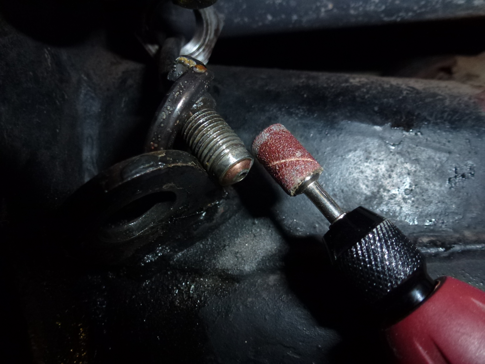
Since the flare nuts are original to the car and thus 45 years old, the new DIN standards since then have probably changed just a bit. I looked to drilling the interior threads just a hair to allow the flare nut end to fit into them, but the choice of bit sizes meant taking off about .007", while I only needed a couple of thousands. Further, it would be difficult to get everything aligned so the bit would cut evenly in the threaded hole and it would be possible to really screw up the threads. In the end, I ended up using a small drum sander bit in the Dremel and by hand spinning the flare nut while the Dremel took off a couple of thousands off the outside of the unthreaded portion.
Once that was done, the flare nut screwed right in, so the rear was done. There is only a single hose since the rear axle is live, thus a hose is only needed from the hard line on the body to the T mounted on the differential.
So back to the left front. It was tighter, but the same process was done to remove some of the material at the end of the flare nut. Then the new hose fit on nicely. I noticed that the lock washer under the nut for the hose fitting was missing, but I didn't have a 16mm one handy. So I moved to the right side. There, the new hose fit onto that flare nut like it is supposed to, so in less than 10 minutes that side was done.
With a trip to Ace Hardware, a 5/8" lock washer (close enough to 16mm) was bought. After applying a black oxide coating and installation, the left side was finished up. Then with bleeding and a test drive, the 330 is ready for Ferrari Day at Exotics@Redmond Town Center next weekend.
Argh, on the way back from an Exotics@Redmond Town Center cars and coffee a couple of years ago, the LF brake started dragging. By the time I got home (a couple of miles), the disk was pretty hot. After it cooled down, I took off the wheel and couldn't find any issues. The disk turned OK and there was no dragging. The only thing I noticed was that there was a bearing noise when I spun the hub. There was a FCA regional concours coming up, so I put the wheel back on and had no issues driving to or from the concours. After the concours, I put the car back on the lift and took all of the wheels off to get them painted as I lost ½ point due to chips, etc. Since the rotor was scored, I decided to take the hubs to the machine shop, have the bearings checked and the rotors turned. Once I got the left hub off, it was clear that there was a bad bearing. Several of the balls were missing. I'm not sure where the pieces went at there was no chunks inside the hub.
So the hubs are at the machine shop to get the bearing replaced, the other bearings checked and the rotors turned.
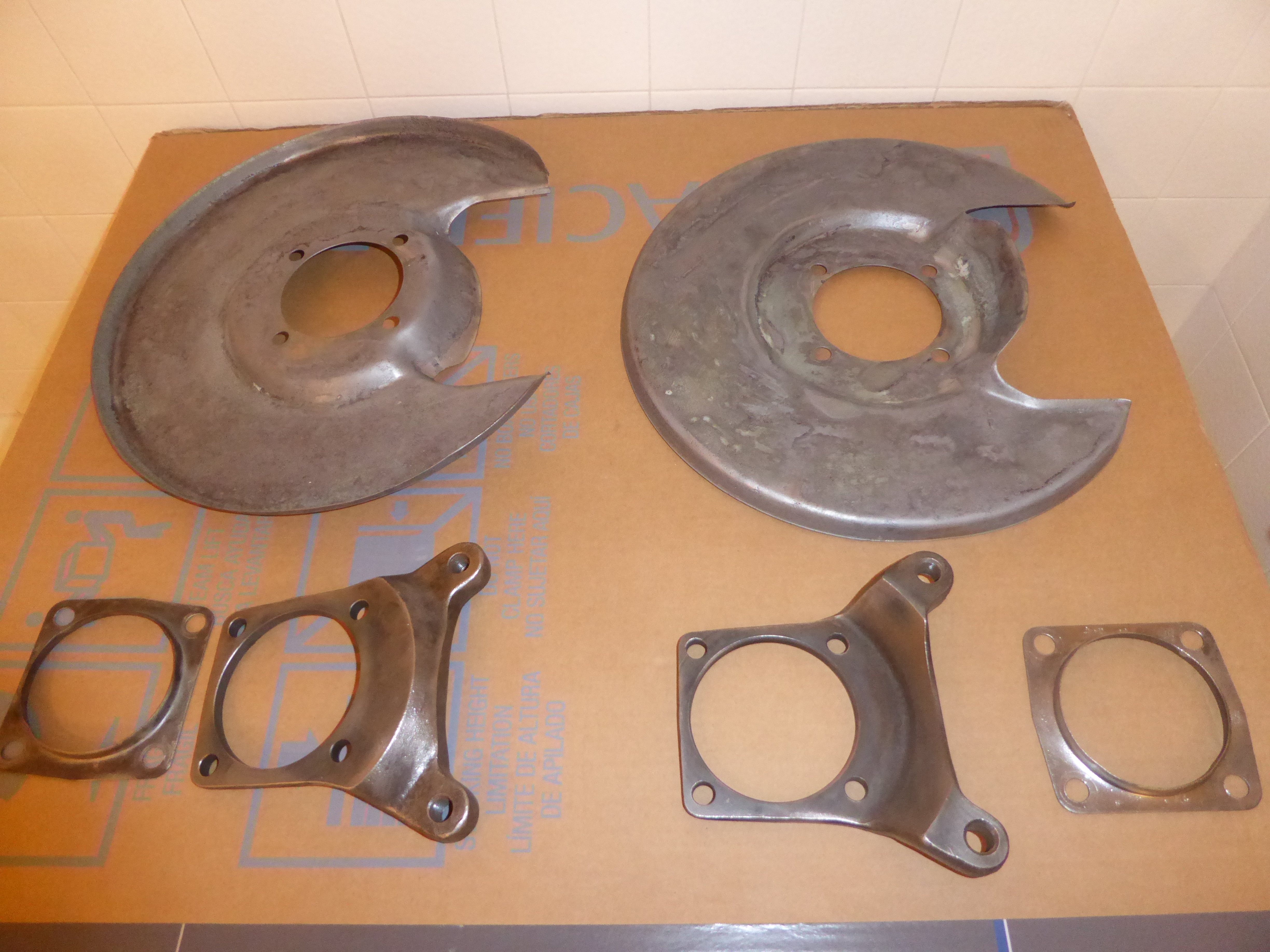
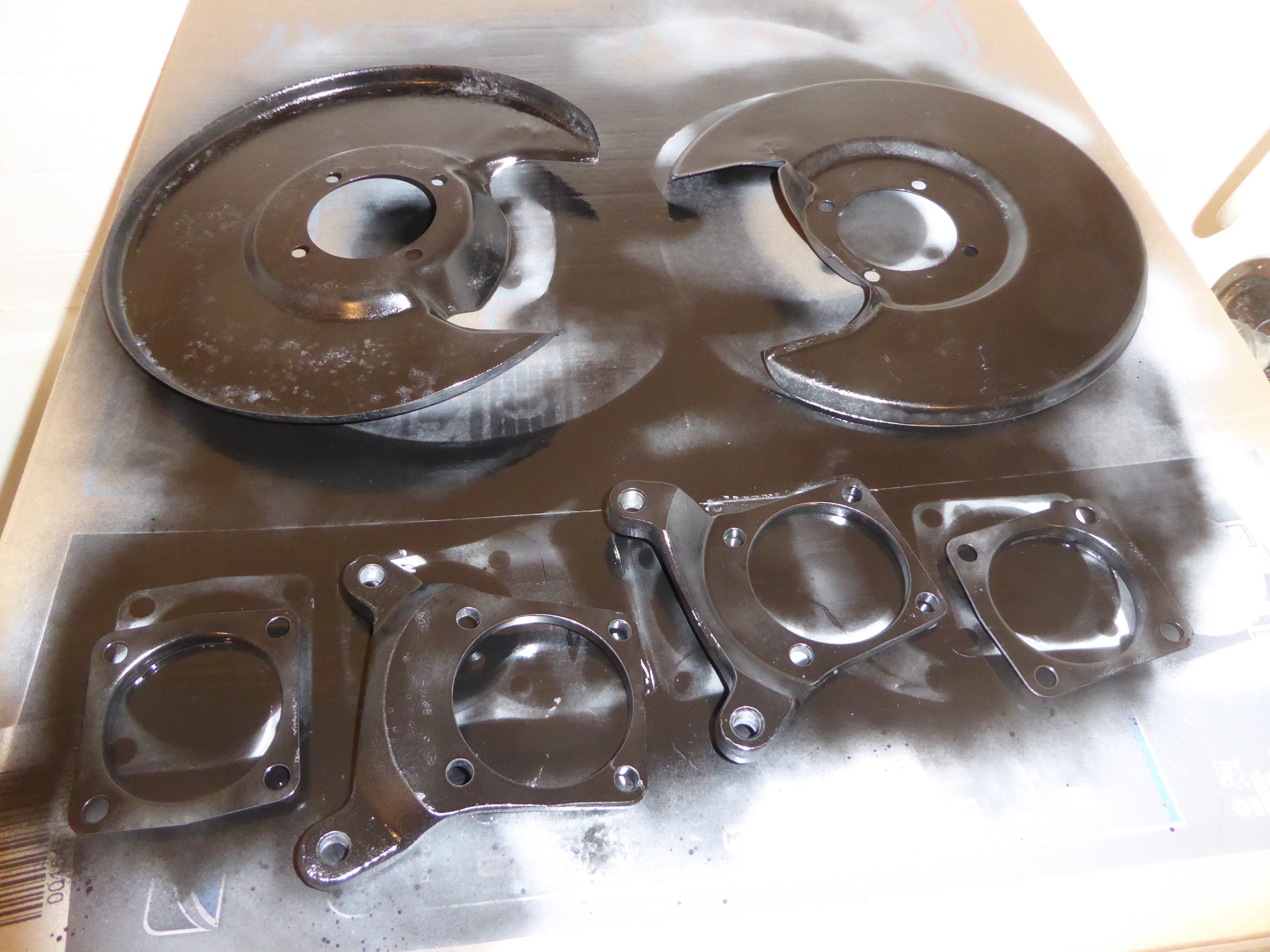
It took forever to get the hubs and rotors done. In the meantime, I decided to remove, clean and paint the dust shields at the insides of the front rotors. First, I started just using the media blaster, but that proved to take too long as the paint was very hard to remove. I ended up using a wire wheel on a grinder and it only took an hour or so per shield. A final cleanup with glass bead got all of the places the wire wheel couldn't get to. Here are the parts before and after painting.
My neighbor was helping me as he wanted to use the lift to work on his Jeep. So, the work was split. Once the parts were dry and hard, I put them on the car and then fit the hubs and rotors onto the spindles. I had marked each hub for right and left as the knock-off threads are left hand on the left side of the car and right hand on the right. I had forgotten that the bearings were essentially a press fit on the spindles. I ended up pounding them on with a 2x4 block and a hand sledge far enough for the spindle nuts to have a few threads. Then tightening the spindle nut pulled the hubs down tight. The last hassle is getting the spindle nut aligned to the cotter pins can fit through the spindle holes. Then getting the ends apart and bent tight is difficult since the spindle nut is recessed about 2" inside the hub. Eventually I got the hubs back on the car and my neighbor helped me put on the wheels. He was having trouble starting the knock-off and when I checked, I mixed up the hubs side to side. As I still have to replace the brake master cylinder, fit new pads and bleed the brakes, we just left the hubs on the wrong sides and dropped the car onto some Go Jacks to move it out from the lift area. When I get the lift back, I'll have to swap the hubs at the same time I finish the brake work.