Four Post Lift
I built the shop in 2002 and now eight years and two more cars later, I'm finding that I always having to play musical cars. In general, the PF coupe is on the lift and the 330 underneath it. So to do anything on the coupe, I've got to move the 330 outside which is an issue if it's raining (and I live near Seattle!). To use the lift for any other car, I've have to move the 330, lower the coupe on GoJaks, roll it out from under the lift and then reverse everything after I'm done. So to make the shop more useable, I ordered a Dannmar Commander 7000 (formerly D-7) four post drive-on lift. This will let me stack two cars and be able to get the 330 out from under the two post lift.
This lift is going in the far end where there are two 7' wide sliding doors. Today I park 2 cars side-by-side at a slight angle and can drive either out. The 4 post lift is just under 9' wide, so even if I have the ramp line up with the side of the door opening, it will be a tight fit if I want a car along side. In addition, there is a truss just over 9' high that is 10' inside of the door, so I have a vertical clearance problem. I chalked a location on the floor, but I think I'll wait until I can set the posts on the prospective locations to see how things fit and where I want to install it. If I move the lift farther away from the door, then there is a better angle to drive a car along side. In addition, the location of a car roof on the upper lift would fit between the trusses, thus solving my height issue.
I downloaded the installation instructions and they leave a lot to be desired. None of the tab A into slot B stuff, just cryptic sentences with perhaps a diagram. After a couple of readings, I'm sure that there will be a lot of trial and error during the assembly. I'm hoping that a newer manual will come with the lift.
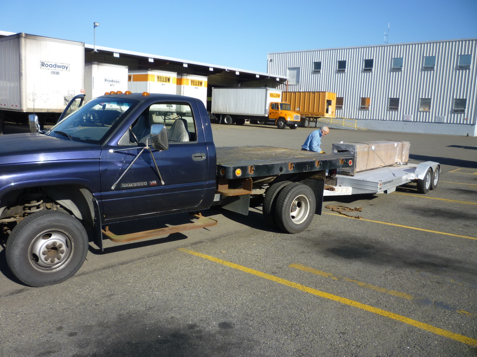
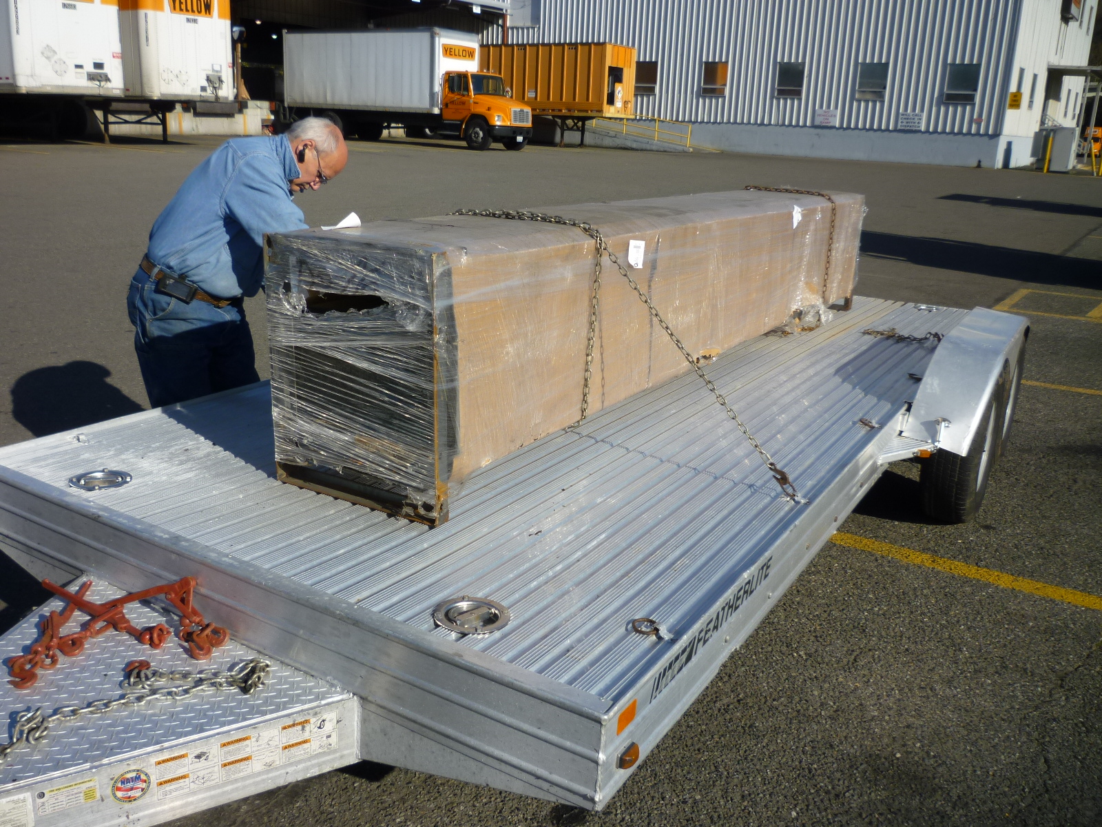
Getting a lift delivered to a residential address is difficult. The freight company charges extra for lift gate service and that doesn't work well given the length of the components (14' for the ramps). So I elected to have it delivered to the YRC freight depot in Seattle. I rented a low boy trailer and the freight company loaded it using a fork lift.
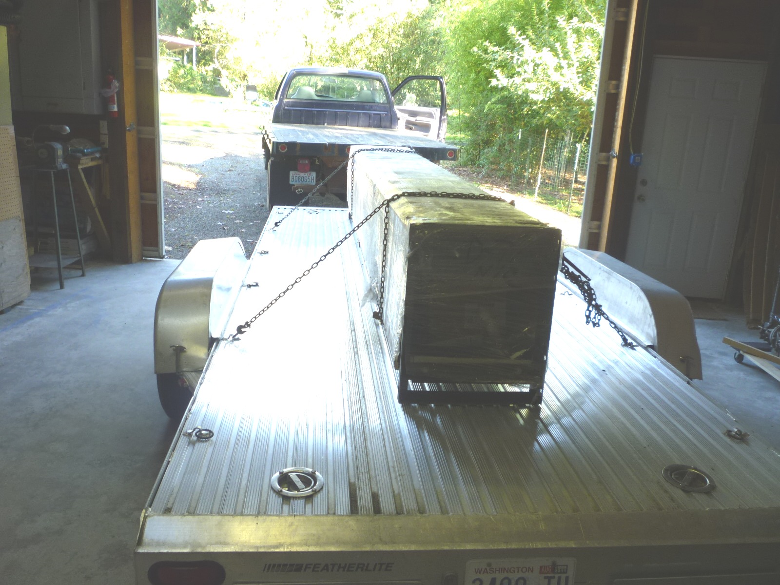
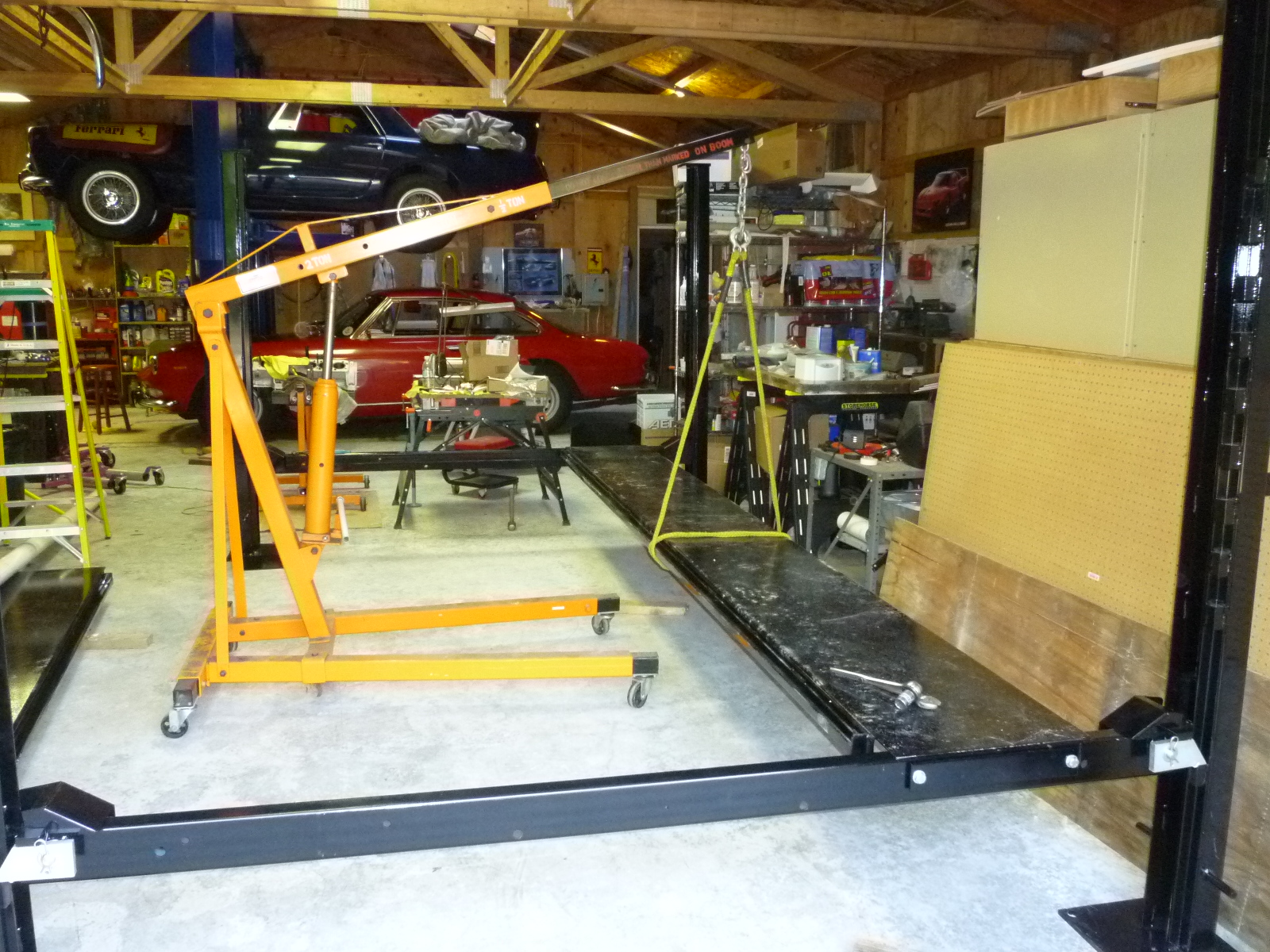
Once back at home, we backed the trailer into the shop and used an engine hoist to lift the whole package off the trailer in one piece.
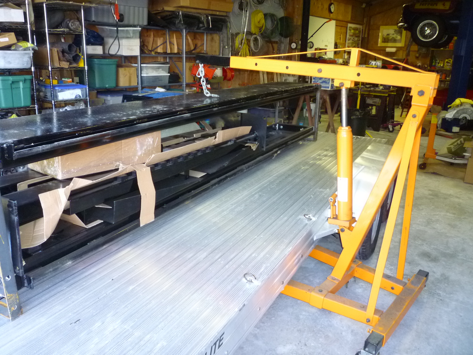
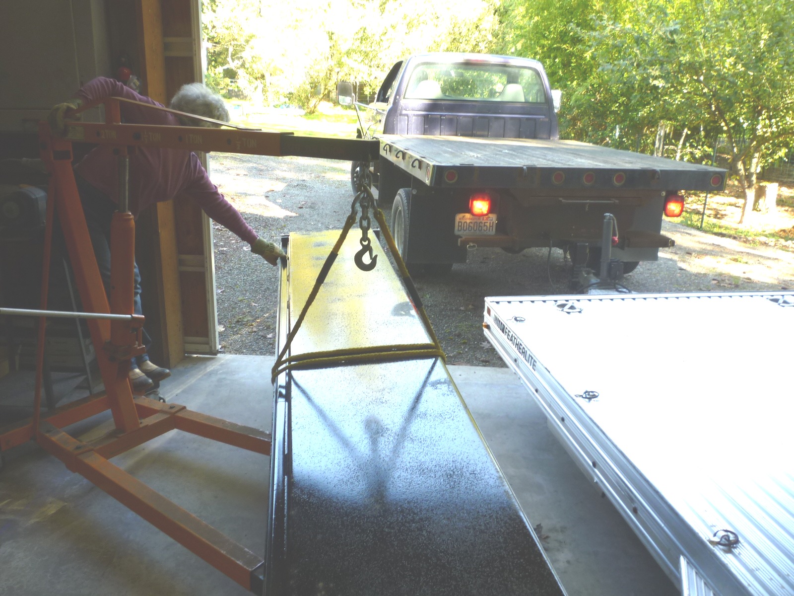
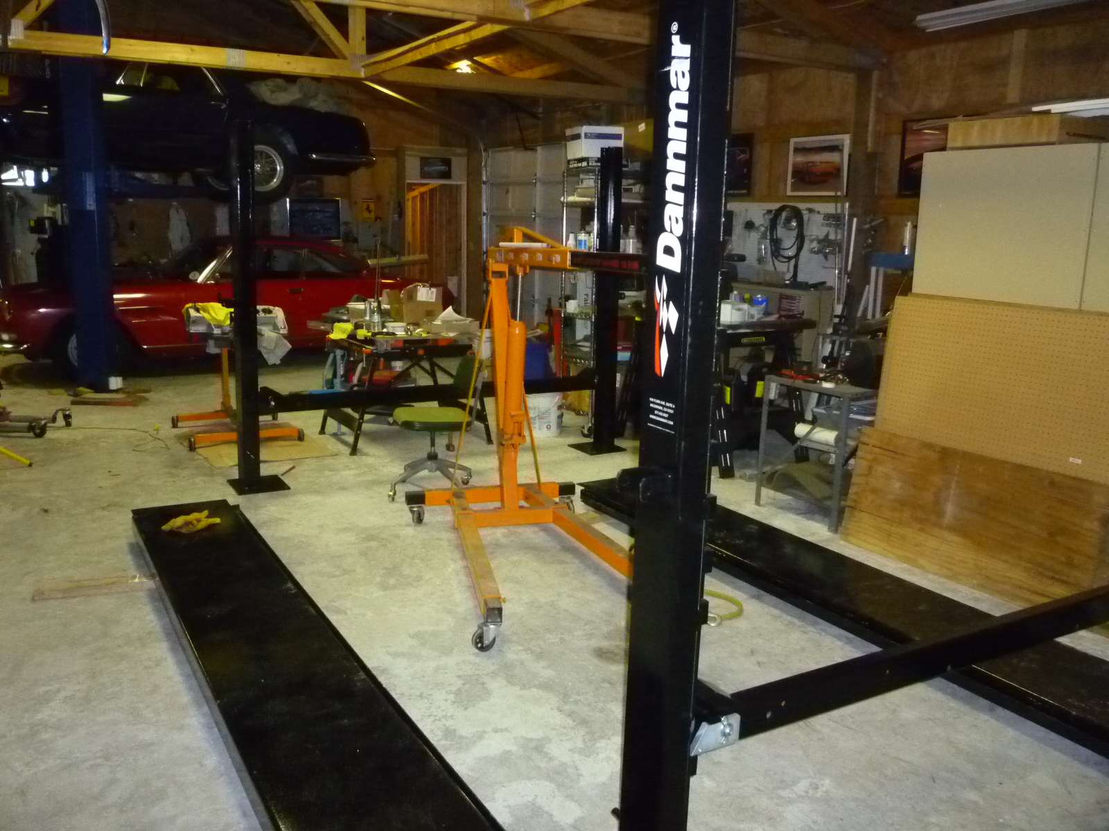
With the trailer out of the way, we started taking the pieces out of the shipping crate. As you can see in the picture above, everything was packed between the two ramps that were bolted to welded framework at each end. The heaviest single piece was the ramp with the cylinder attached. That was about 300 lbs, but it was easy for two people to move it an end at a time. Once everything was unpacked, I set the four posts in my prospective corners to determine if my plan was going to work. Here you can see the four posts with their cross pieces in place along with the ramps still on 2x4s on the floor. Of course both ramps needed to be swapped end for end as they came out of the packaging the wrong way to.
That's as far as I got today, so more assembly will have to wait for tomorrow.
Well, the instructions that came with the lift are identical to the downloaded one. Plus, not only are they sparse, Dannmar has changed a number of items since the instructions were written in Dec. 08. Among others, all of the hardware is now metric. So instead of a ½"x4" bolt, the parts list shows a 14x100mm bolt. However, the instructions still say ½"x4", so one's metric conversion skills get a workout. In addition, several Nylok nuts are now flat washers, lock washers and regular nuts. I ended up with extra hardware that I had to go back and figure out where it should have gone.
I also found that the hairpin clips holding the safety locks was oriented incorrectly at the factory. The clips were positioned vertically, thus covering the area where the safety bar hardware needed to mount. So that was an extra ½ hour removing the pulley covers, loosening the two Allen set screws and turning the pin so the hairpins clipped in horizontally on each of the four corners. At the same time, I centered the pin front to back as three of the four locks were so tight that they could be rotated using ChannelLock pliers but the spring would not flip them back in place. If this happened as you were lowering a car onto the safety blocks, that corner would continue to lower and the lift could collapse, particularly if the posts aren't bolted to the floor.
|
|
|
The instructions also assumed that the post with the hydraulic pump would be at the far left corner as you would drive a car onto the lift. The alternate location is the right rear where I put it for easy access to an electrical outlet. So I had to check that each instruction was correct for the alternate location.
Having an engine hoist is almost essential to easily assemble the lift. Almost all of the heavy work was accomplished using the hoist. The only heavy parts to be man-handled were lifting the two crossbars and dropping them down into each pair of columns. Of course, both ramps were the wrong way so they had to be lifted and spun around. Here the first ramp is being installed.
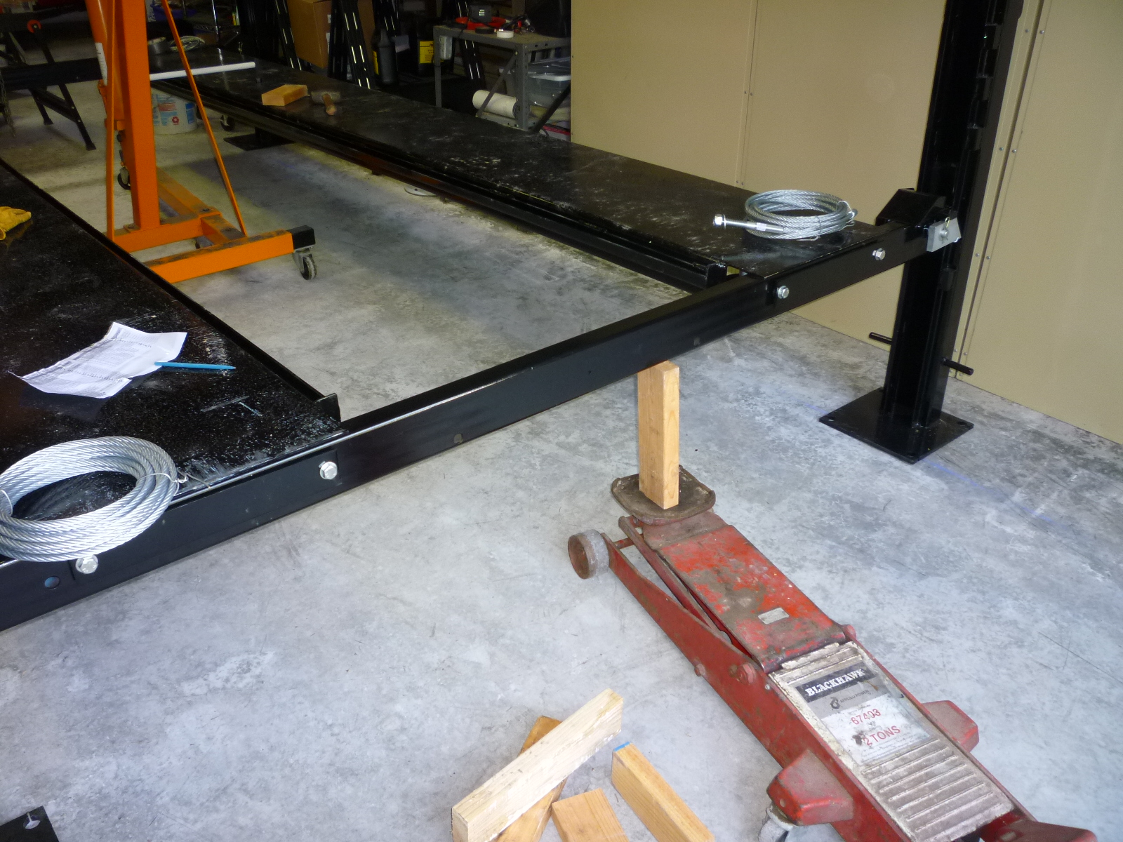
Once the platform was assembled, I raised it up to the second set of lock blocks to make it easier to use a creeper under the ramps for installing the cables and hydraulic hoses. I used the engine hoist at one end and a garage jack at the other to raise it up. I haven't used a creeper in a number of years (since installing the 2 post lift). In the meantime, I now have my hair longer and in a pony tail. The first time I rolled the creeper back, my hair went under a wheel and boy did it hurt. After that, I was careful to keep my hair tucked on top of the foam headrest.
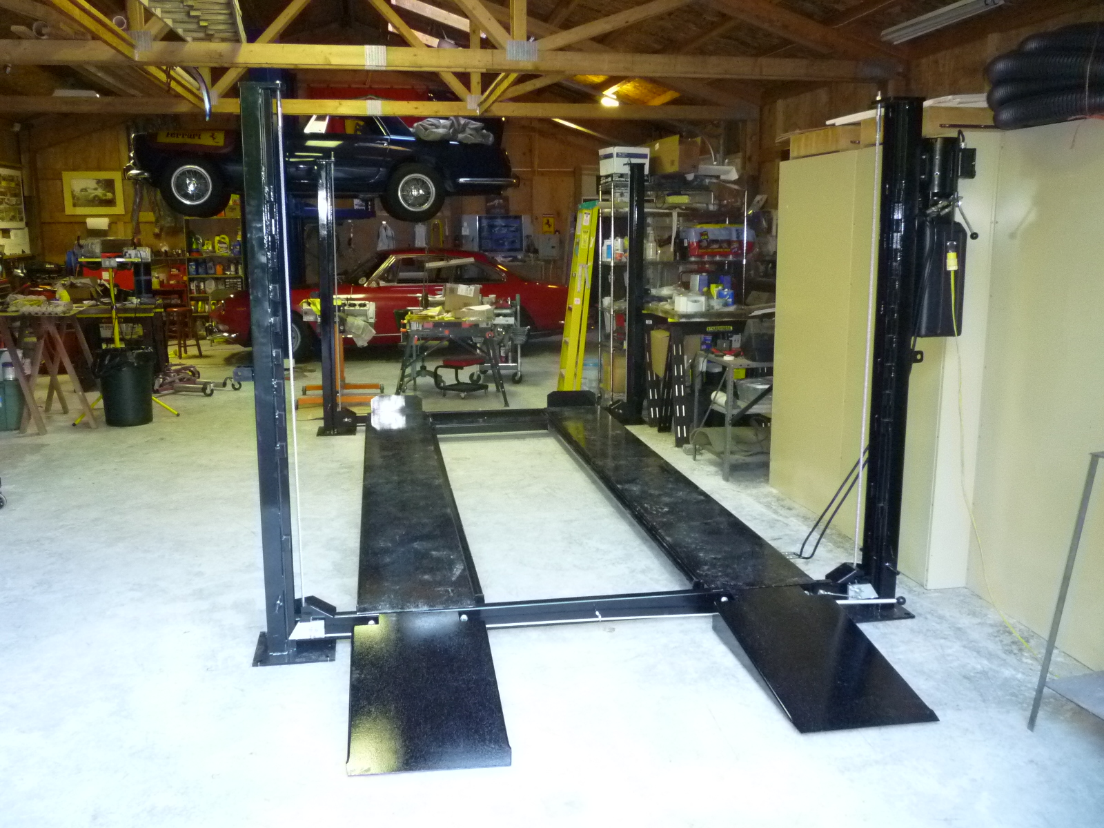
I got everything done except for the final adjustments. I need to adjust the assembly that releases the safety locks when lowering the lift and the cables for equal tension . So just another hour or so until completion.
The other thing I think I will build is a cut-off switch using a NC (normally closed) pushbutton switch with an outlet attached to the truss above the lift. That way, if a car is raised too high, the switch will stop the lift before the truss is hit and the car roof creased plus there won't be an extension cord running across the floor
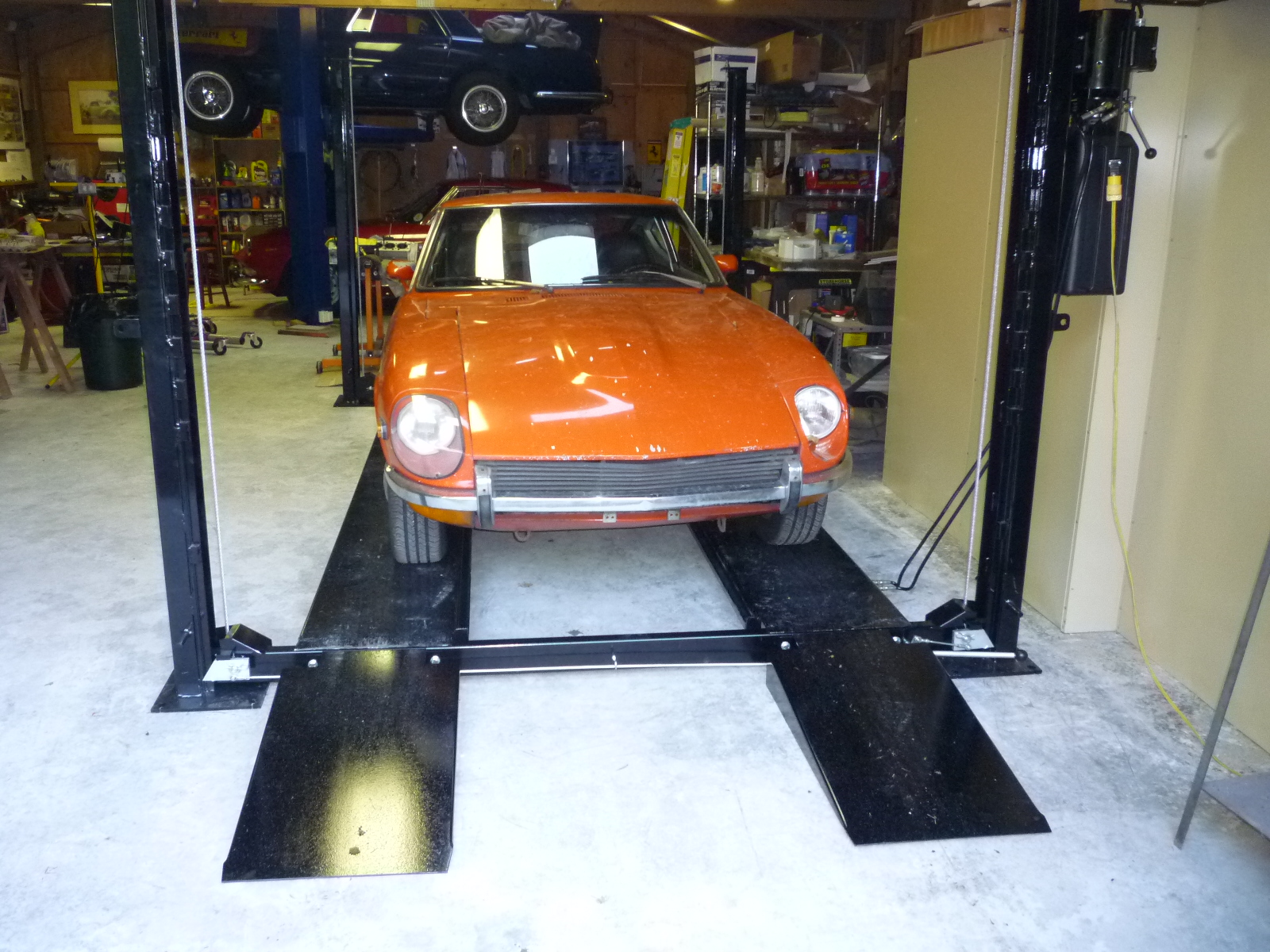
I bled the hydraulic system and raised the lift enough to adjust the safety lock system. You really need to have the lock nuts tight on both side of the coupling nut tight and they are a bear due to limited access. After that, I lowered the lift so the safety locks were just above the lowest set of lock blocks. Then I adjusted cables so each corner was the same distance above the lock blocks by tightening the Nylok nuts on the end of the cables. Here's the final assembly and in use. Since the Z is a hatch back, it was backed onto the lift so the hood area was under the truss. There is enough clearance to raise the lift to the top stop.
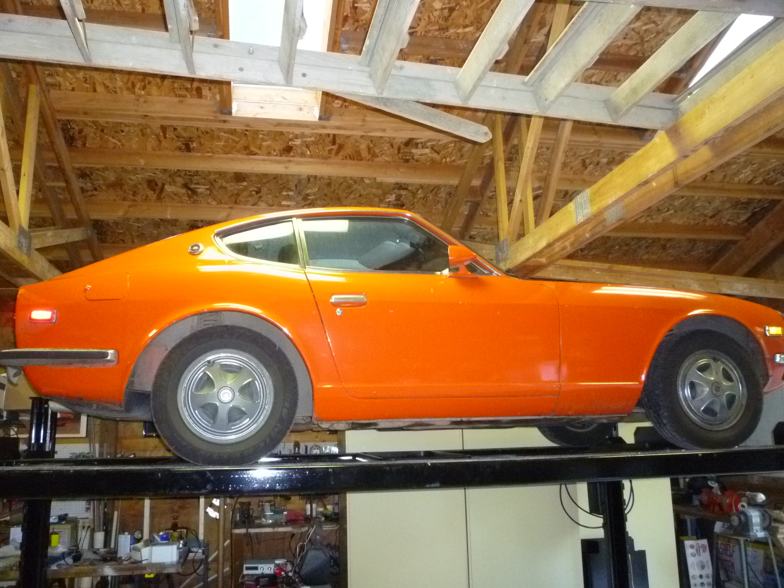
I was disappointed in the size of the three drip trays. I was expecting that they would fit together and completely fill the center of the lift from one end to the other. Instead, they only cover about 2' each, so I had to position one under the differential, the second under the rear of the transmission and the third under the front of the engine. I'm just glad that the Z only leaks from three places.
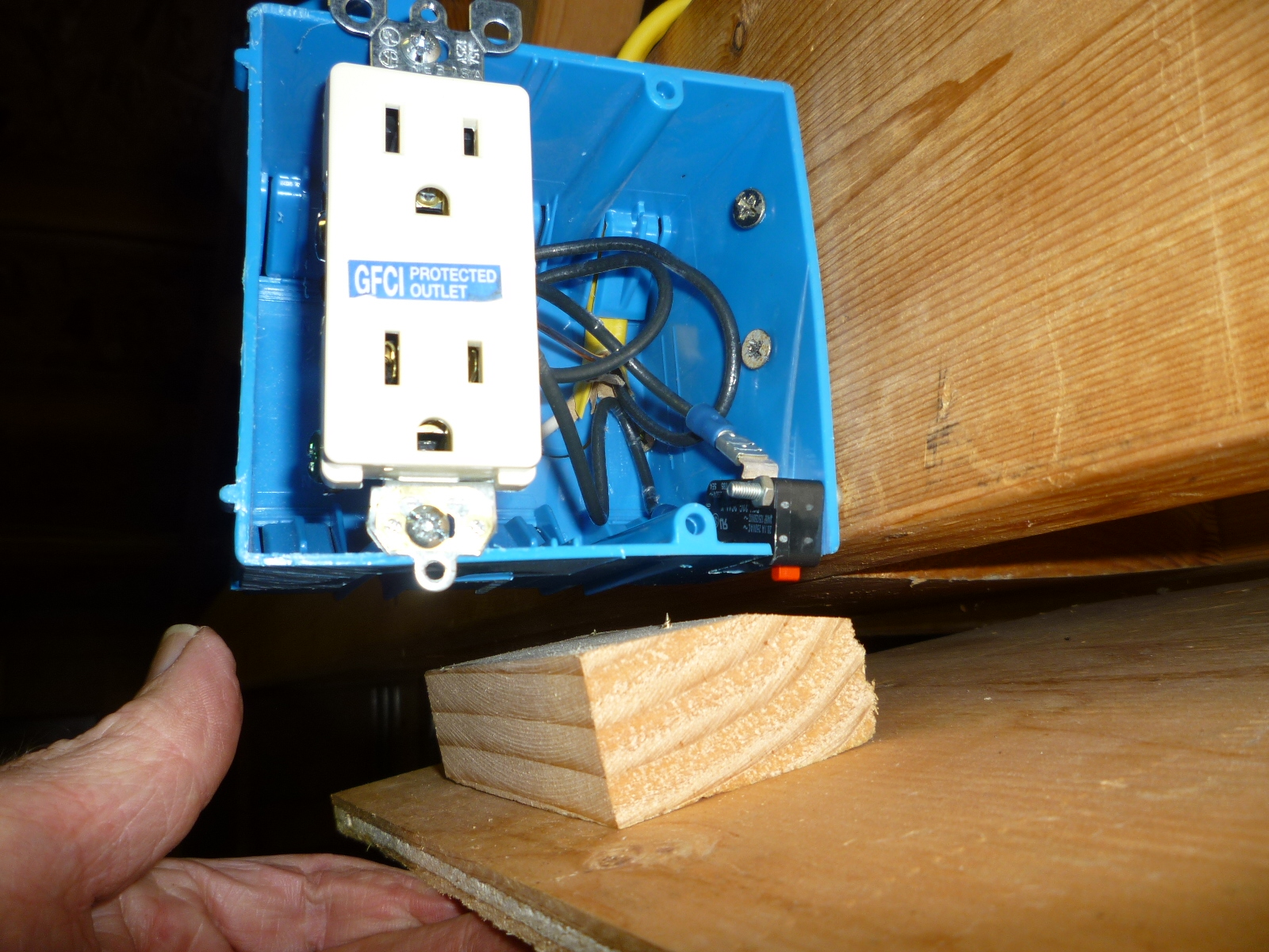
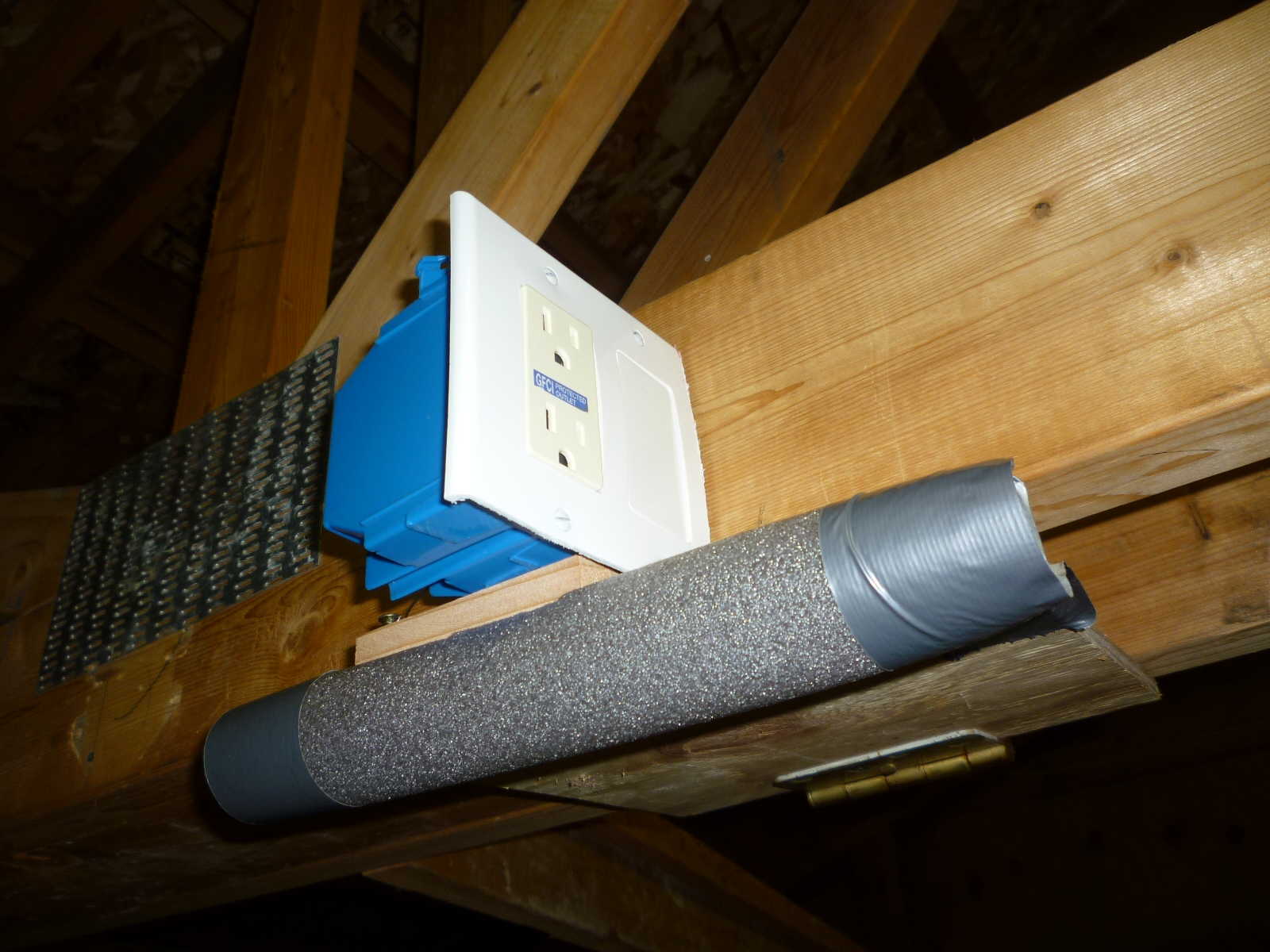
I did end up building a safety switch to prevent a car from being raised into the truss. The design was pretty simple, a normally closed switch mounted in an electric box that switches power to an outlet in the same box. I spent some time finding an adequate switch, but came up with a 125V 20.1 amp switch at Grainger. Most of the switches are 3 amps or less and the contact wouldn't last in this application. A piece of ¼" plywood was hinged on one side of the truss with the switch mounted on the other. I covered the plywood with some foam so it wouldn't scratch any paint and added a block to push on the switch. That way, if the safety locks just happened to click in just before the switch cut power, I can remove the block and have enough room to raise the lift enough to release those locks and lower the car.
In the midst of the assembly, I had a long online chat with a manager at Garage Equipment Supply who are either the distributor for Dannmar or at least handle their customer service issues. I was trying to get some clarification where an external ring went along with a couple of extra parts and exactly how the tie plate and keeper go together to attach the cable ends to the piston rod, none of which are addressed in the instructions. They know that the instructions are poor and are in the process of revising them. I complained about the extra time spent in figuring out things and then having to redo a couple of things where I didn't figure it out correctly the first time. I offered to review the revisions, so hopefully I can update this page sometime in the future with better news.
In the meantime, for those installing a Dannmar 4 post lift, these tips are in addition to or clarification of the instructions from Dannmar. You need to judge each for applicability and safety in your specific installation.
-
Unless you have access to a loading platform and fork lift, I suggest having the package delivered to your local freight depot and using a low flatbed trailer to pick it up there. Even with a lift gate and pallet mover on a delivery truck, I don't see how a 14' package can be delivered easily, plus you want it placed on the floor near where you want to install it.
-
It is possible to unload the whole package in one piece using an engine hoist on a 1 ton or higher setting. Since the hoist feet will be under the package, have a couple of 4x4s for each end to sit it down on.
-
The manual use the terms front and rear, but assume that the pump is located on the far left post as viewed when you would drive a car onto the lift with front being at the far end and rear being at the near end of the lift. If you put the pump in the alternate location on the near right post, the front and rear concept are swapped (see #15 below). In this write-up, I use near to mean the end where you drive on the lift and far to be the other end, independent of where you place the pump post. Left and right correspond to the left and right sides of a car as you would drive it onto the lift.
-
The manual specifies that 60" of clearance is needed on the safety handle (pump) side of the lift for linkage installation. This is not true, the only side clearance needed is at the pump side is for the installation and operation of the pump. However 120" of clearance is needed at the end away from the pump post for installation of the long piece of the safety bar. If you are placing the far end of the lift near a wall and also putting the pump on the near corner, you will have to assemble the lift away from that wall and then move it after the long piece of the safety bar is in place. Of course, if you bought the optional caster kit, that isn't a problem. Installation of the handle piece of the safety bar requires about 4' of clearance at the pump end. The drive-on ramps are 38" in length, so if you want to leave them attached, you will need that amount of clearance to be able to close the garage or shop door.
-
Be careful when stripping off the plastic wrap and cardboard. The Nylok nut on the end of the piston rod had vibrated off and was loose in the package.
-
When unpacking, get the ramps oriented correctly to start. The one with the cylinder goes on the pump side. For both, the sides of the ramps with the U-channel go to the center of the lift. Spinning them around once the posts and crossbars are in place is difficult due to the length and weight. I read that one owner used some furniture dollies to rest them on when unpacking. That would make moving them around much easier and safer than having to pick one up and then moving the hoist and the suspended ramp together.
-
The hardware bolting the package together is not used in assembly so it can be discarded.
-
Think about where you want the engine hoist to be. Mine ended up inside the platform due to the way I unpacked the ramps. Once the crossbars and ramps are installed, I couldn't remove the hoist until the lift is operational so it was in the way for the cable and hydraulic hose installation.
-
Check that each safety lock on the crossbars rotates easily and the spring returns it to the resting place. If not, see #23 below to adjust the pin.
-
I didn't do this, but in hind sight, I would try laying the posts down flat with the tops toward the center of the lift and with the lock blocks up. Slide the crossbars all the way to the post bases. Might as well bolt the post caps on now too. Then raise both posts into place with a helper. Much safer than two people on ladders trying to lift and fit the crossbars into the top of the 7' high posts which aren't very stable.
-
If you install the crossbars with the posts vertical, double check that you have the lock blocks on each post oriented away from the center of the lift. Make sure that you have the crossbars oriented correctly with the safety locks facing away from the center of the lift so they match the post lock blocks. If you can slide the crossbar down without having to release the locks, you have it wrong.
-
Sort out all of the nuts and bolts and compare to the packing list. The 18mm washers and Nylok nuts specified are screwed on the cables unless they vibrated off like one of mine did.
-
As you go through the instructions, convert the US sizes to metric, check the quantity and use the corresponding hardware. Here's what I used where:
QTY
Item
Location
8 M6 FEMALE ROD END
Safety rod ends
8 M6 HEX NUT 4
M6 x 30 HEX HEAD BOLT Attaches safety rod ends to safety bar plates
4 M6 FLAT WASHER 4 M6 NYLON LOCK NUT 4
M6 x 35 HEX HEAD BOLT Attaches safety rod ends to safety locks
4 M6 FLAT WASHER 4 M6 NYLON LOCK NUT 2
M6 x 120 EYEBOLT
Supports for middle of safety rod
2
M6 NYLON LOCK NUT
1
M16 COUPLING NUT
Attaches short and long safety bar pieces together
2
M16 HEX NUT
4 M8 x 25 HEX HEAD BOLT
Attaches pump to post
(with foam dampener in between)4 M8 NYLON LOCKNUT
4 M12 x 30 HEX HEAD BOLT
Attaches post caps to posts 4 M12 FLAT WASHER 4 M12 SPRING (lock) WASHER 4 M12 HEX NUT
8 M14 x 100 HEX HEAD BOLT Attaches platforms to crossbars 16 M14 FLAT WASHER 8 M14 SPRING (lock) WASHER 8 M14 HEX NUT 2 SAFETY SPACER At each end of safety bar 2 SAFETY SPACER Spacer for eye bolt? 1 TRUARC EXTERNAL RING 5103-87 End of piston rod 20 SHIMS 10 thick and 10 thin, used under posts as needed
if bolting the posts to the floor (which I recommend) -
Convert the cable lengths from metric to US to figure out which cable goes on which corner. Of course, if you are installing a D-7X, the cable lengths are different than these.
Item Part # Length as shown
in instructionsD-7 CABLE ASSEMBLY 6502mm 17055005 256" D-7 CABLE ASSEMBLY 7925mm 17055006 312" D-7 CABLE ASSEMBLY 4013mm 17055007 157" D-7 CABLE ASSEMBLY 2591mm 17055008 101" -
When looking at the diagrams and instructions, remember which corner you are putting the pump on and make sure that the instructions are correct for that location.
-
The instructions call for setting the crossbars on the lowest set of lock blocks. This minimizes the likely hood of the posts falling over before the ramps are installed since the weight is lower. It's also easier to install the ramps since they don't have to be lifted as high. However, once the ramps were installed and bolted down, the lift is stable, so I raised the platform up to the next set of lock blocks to have more room to install the cables and hydraulic hoses under the ramps.
-
When installing the cables, stick the threaded end up through the post top and hand thread the washer and Nylok nut onto it. Then run the swaged end through the various pulleys and back to the tie plate. You don't have to take apart any pulleys to run the cables. Do not thread a cable through the round brackets under the ramp with the cylinder.
-
When running the two long cables from the pump end, it is hard to get them around the upper double pulley. I found that sticking the end of the cable out the opening on the outside of the ramp and then looping it back through so you only had to bend the cable 90° instead of 180° was much easier. Then pull the extra loop back inside the ramp.
-
When extending the piston rod to attach the tie plate and cables, the easiest way is with a air blow gun. I installed the 90° fittings, but temporarily left them pointing down for use with the air blow gun. The port closer to the pump extends the piston rod while the farther port retracts it.
-
When assembling the parts on the piston rod, the order is the thick tie plate, thin keeper, Nylok nut and external ring. Tighten the Nylok nut down until it runs out of threads and then fit on the external ring. With the cables loose, slide the tie plate down the piston rod and the keeper against the nut. Fit the loose cables into the correct slots in the keeper, and then fit each swaged cable end into the matching slot in the tie plate. Once all cables are in place, slide the keeper down tight against the tie plate. Check that all of the cables are still in the proper pulleys. After getting everything assembled, I retracted the piston rod lightly to keep each cable on the various pulleys. Getting the long cables back on the upper double pulleys at the end of the ramp with the cylinder is particularly difficult so you don't want them to drop off. When retracting the piston rod, be careful as the cables are loose and dangling where you have to use the air blow gun. The piston action is not smooth with air, so the cables tighten in one quick motion. Double check that each cable is run properly, not crossed and fit into each pulley. If the cables aren't run properly, the lift may work, but eventually there will be a cable failure with catastrophic consequences. Once the cables are checked, turn the 90° fittings correctly for the hose installation.
-
The hydraulic hose with the 90° end goes from the bulkhead fitting through the square brackets to the piston end of the cylinder. The other two long hoses go from the pump to the bulkhead fittings with the short hose going to the other end of the cylinder. There was a yellow card packed with the pump that specified to intermittently run the pump with the pressure hose disconnected at the cylinder until the fluid comes out without bubbles to prevent failure or premature wear on the pump. So this is best done before screwing that hose end onto the fitting by the piston rod end.
-
Slide the eyebolts onto the long safety rods before assembling the lock nuts and ends. I found that I had to run a 6x1.00mm die down each end of the long safety rods to clean up the threads.
-
Check that the hairpin clips holding the safety locks aren't in the way of the holes for the safety rod ends. If one is, remove the shield over the pulley, loosen the two Allen set screws, rotate the shaft and re-assemble.
-
Install 6mm washers between the safety rod ends and plates to the safety rod ends are free to rotate.
-
There were 4 linkage spacers in the parts list and the package. Two were used, one at each end of the safety bar, but I couldn't figure out where the other two went. The instructions called for spacers on the eyebolts that supports the linkage safety rods. The eyebolts were changed from 3/16" to 6mm size. Possibly one is supposed to use the two extra linkage spacers for the eyebolts, however using a 16mm diameter spacer on a 6mm bolt is sloppy. Instead, I added a 6mm nut to each eyebolt. That way I could adjust the loop where I wanted it using the nut on one side of the crossbar and the Nylok nut on the other.
My mistakes:
-
The bolts holding the ramps to the crossbars have a flat washer on the outside, flat washer, lock washer and nut on the inside. The inside used to be a Nylok nut so I didn't use a flat washer on the inside, thus ended up with 8 extra washers and had to go back and install them.
-
On the ramp with the cylinder, there are two square brackets to run the hydraulic hose through. On the same side, there are three round brackets. With the warning in the instructions to make sure that the cable isn't near the hydraulic hose, I thought that the cable went through those round brackets to keep it clear. It didn't look quite right, but I couldn't think of any other reason for the brackets to be there. Later, when I went to install the long safety bar, it became clear that the brackets were to support it and not to run the cable through. So I had to disconnect and re-install the cable correctly.
-
The safety rod ends need a washer between them and the plate they fasten to. I had put the washer on the far side under the Nylok nut.
-
I guessed wrong on the order of the tie plate and keeper.