Instruments
All of the instruments came with the car, but the clock needed some work.
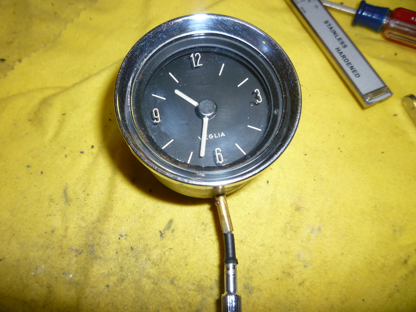
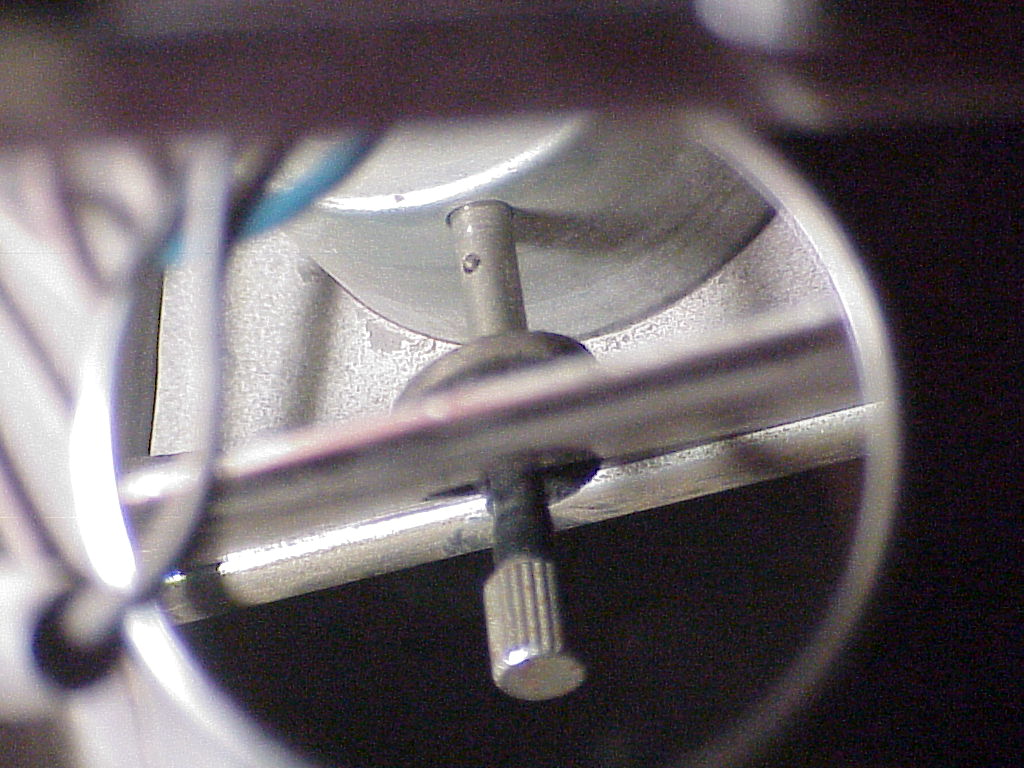
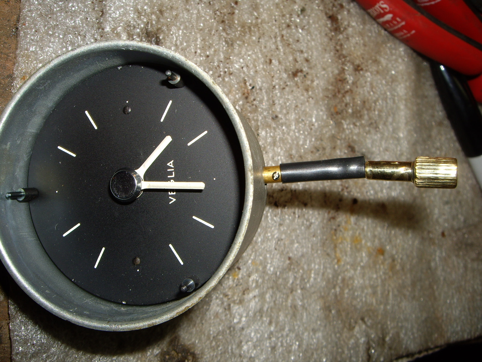
The clock wouldn't work even when wound (this is a mechanical spring driven clock). So I removed the bezel, glass and face to took it to a clock maker. He just cleaned and adjusted the mechanism to get it back in working order. In addition, the flexible tail was missing. Here's what it looks like (picture was taken using a mirror to focus behind the dash).
I bought some brass rod the correct diameter for the knob. I'll use some wound piano wire for the flexible part and some more brass rod to attach the other end to the clock. I am using the odometer reset knob as a model. So far, I have just worked on the knob.
 |
 |
I got to thinking about the tail and realized that I could use the tail from any Veglia clock (or the trip odometer reset cable from a speedometer) from a Alfa, Fiat, etc. So I trolled eBay but was outbid on the couple that were reasonably priced. Then I remembered that Lowell Brown had bought a used speedometer to replace the one in his 330 which had stopped working. So I asked if he still had the old remains and he sent me the reset cable. Then I would just have to mate the knob I made on one end and fit the other end onto the clock.
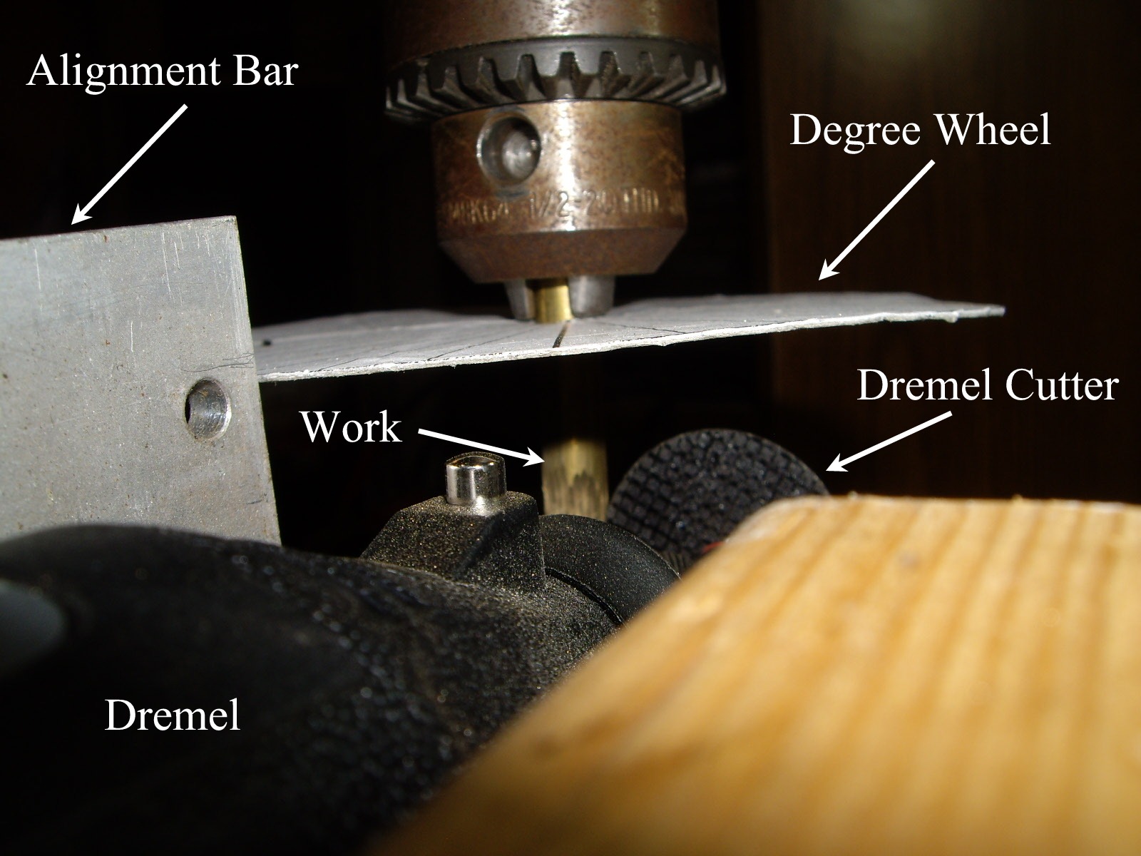
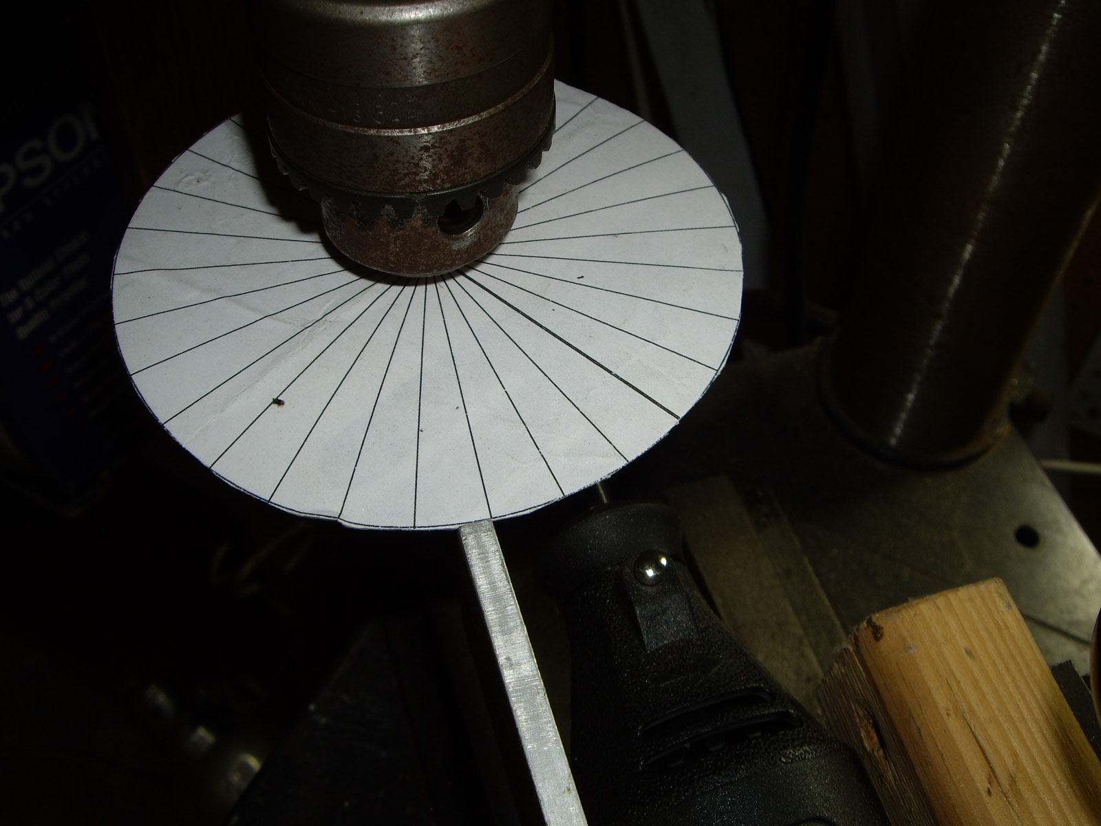
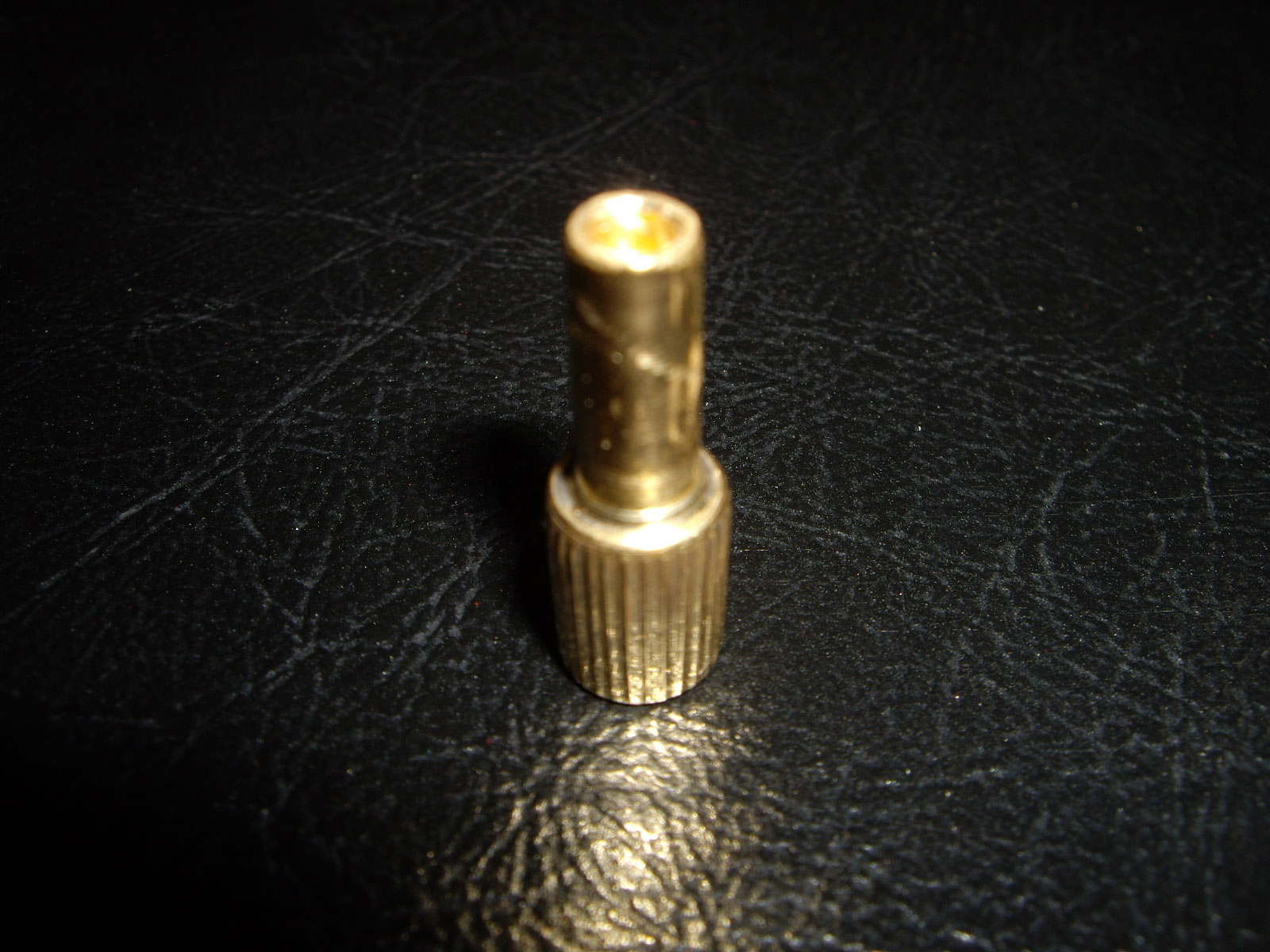
In looking at how to make the knurling on the knob, the right was would be to use a milling machine with a indexing head. However, I figured out a way to do it with the available resources. I first made a degree wheel with every 12° marked since there are 30 grooves. I took a new section of the 5/16" brass stock and chucked it in the drill press with the degree wheel attached at the top. Then I clamped my Dremel with a cutting wheel (which had been made into a V edge) in the vise along with a bar to use with the degree wheel. Using the screw feeds on the vise allowed me to align the cutting wheel so it would cut a groove as I lowered the chuck on the drill press. Note, the drill press was not turning, but simply used to hold the work and allow it to be rotated every 12°. After cutting one groove, I would just rotate the chuck to the next mark and run the chuck down again, creating the next groove. Repeated for 29 times to create all of the grooves.
 |
 |
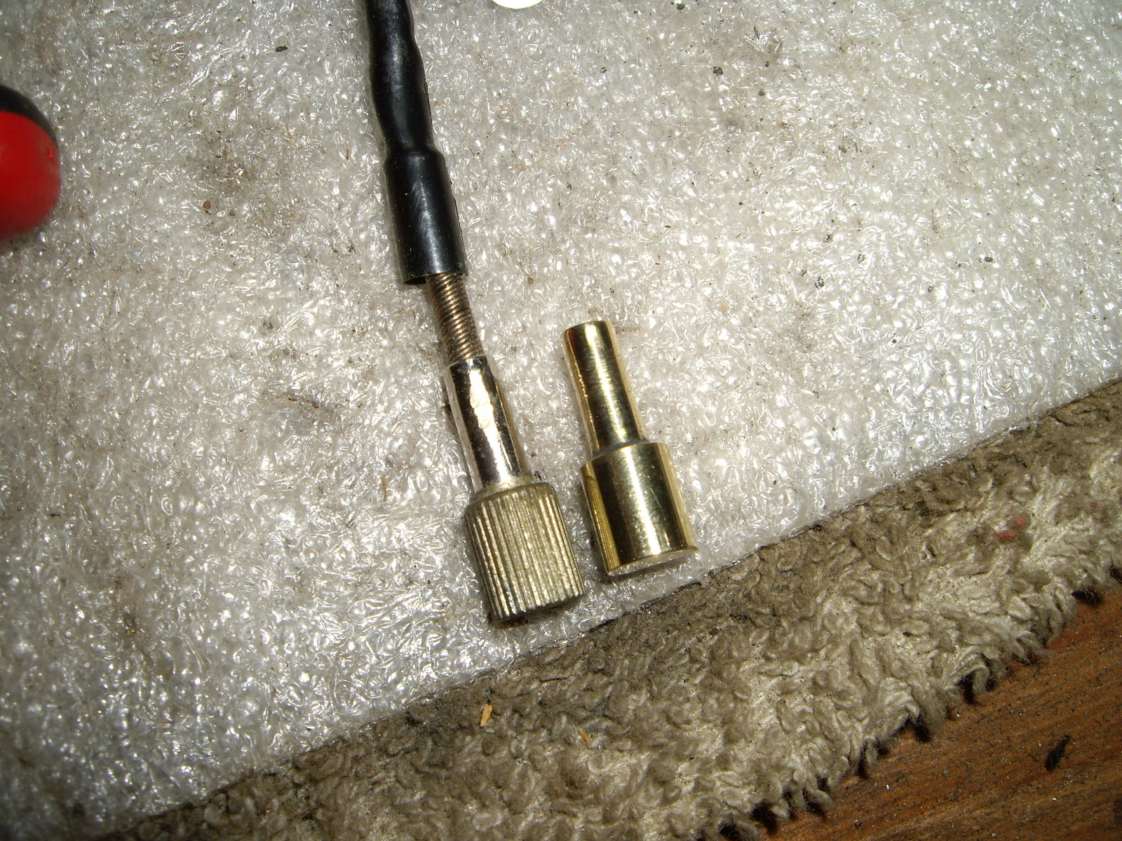
After this was done, I had the knurled end finished. Here it is with the old one that I couldn't use as there wasn't enough shank to chuck it in the drill press.
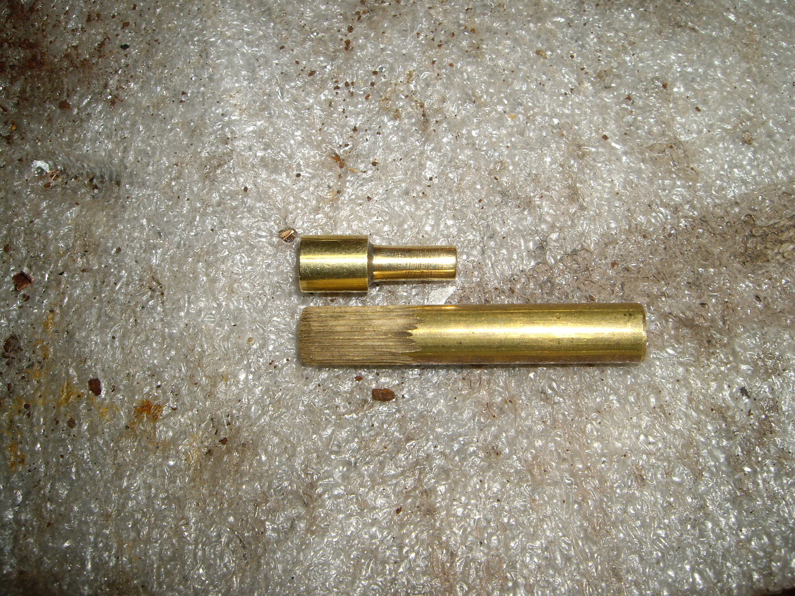
The next step was to turn down the narrow portion, cut it to length and drill a hole in the end where the spring wire fits. Here's the finished knob after being buffed and polished.
Next, I took the trip odometer reset cable from Lowell and cut off part of the end where it screwed onto the speedometer. I drilled a hole in that end large enough to fit over the shaft coming out from the clock and then a small cross hole for the screw that attaches it to the shaft.

Then I put the clock into the dash to determine how long to have the spring portion. Once that was done, I cut the spring wire at that the right place and fit the knob onto it. I'll wait until I have the knob chrome plated before crimping it onto the spring. I'll have to have the other knob (trip odometer reset) chromed at the same time so they will look alike.
All this because someone didn't pick the tail off the table where Tony Nancy was working on the re-covering the dash.
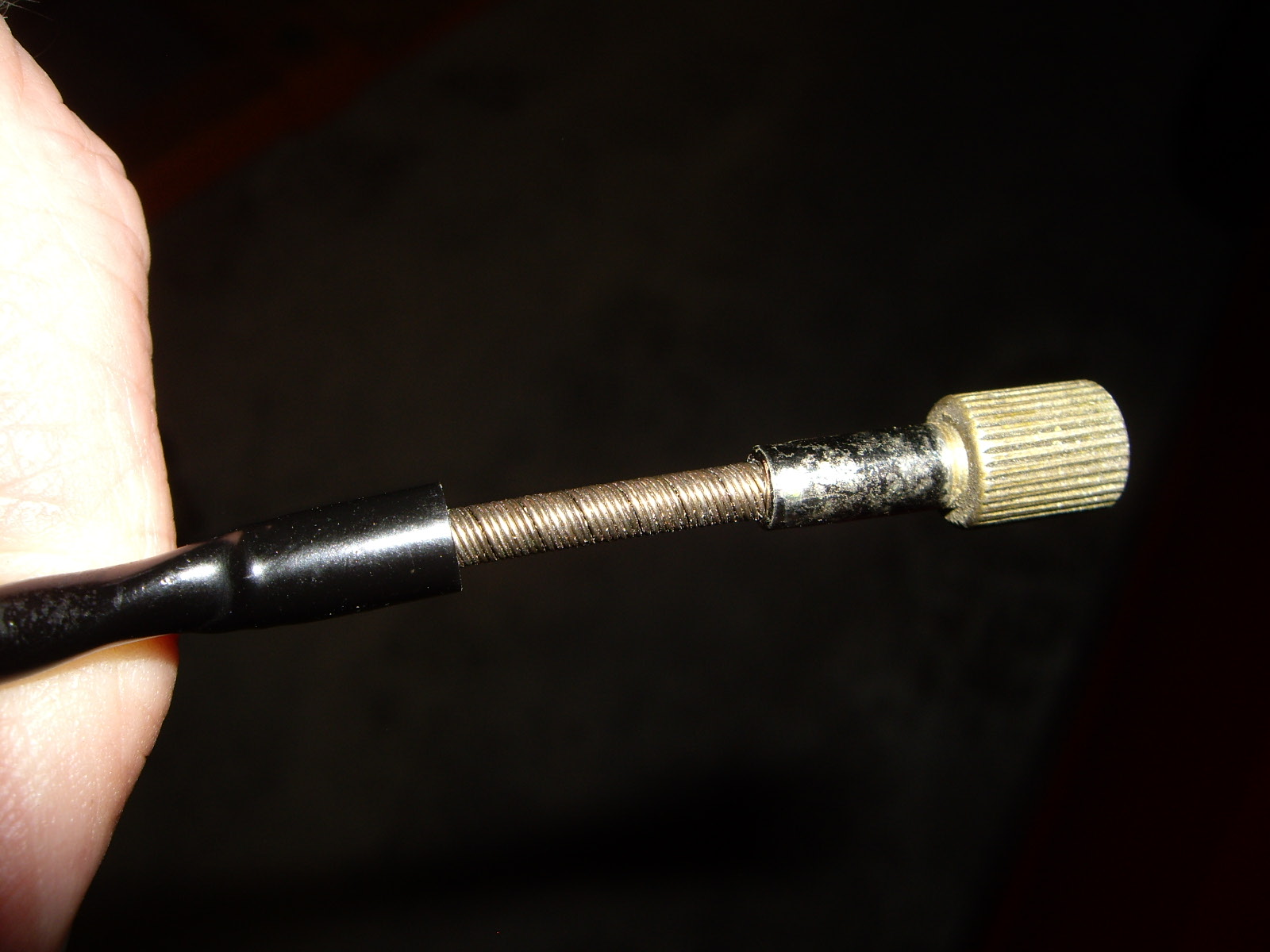
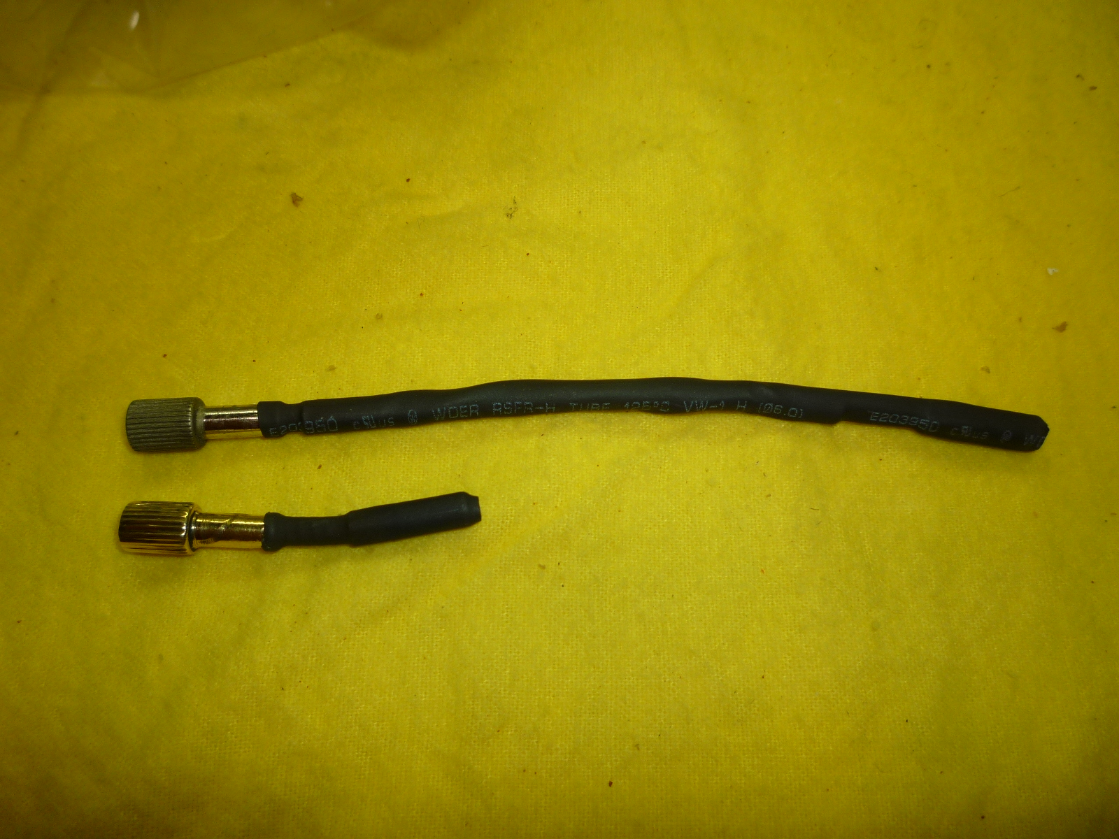
I forgot to get the clock tail chromed when I had my first batch of chroming done, but I'm putting together another chunk of parts. I decided that I had better get the odometer reset tail done on the speedometer at the same time or they wouldn't look right together. In the picture, they both have shrink wrap tubing over the flexible part so that part doesn't get chromed.
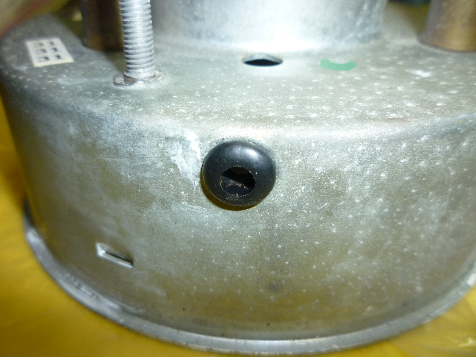
So I pulled out the speedometer from the dash where it was temporarily installed to test the wiring. The tiny screw that hold the tail on is accessed through a hole in the back of the speedometer.
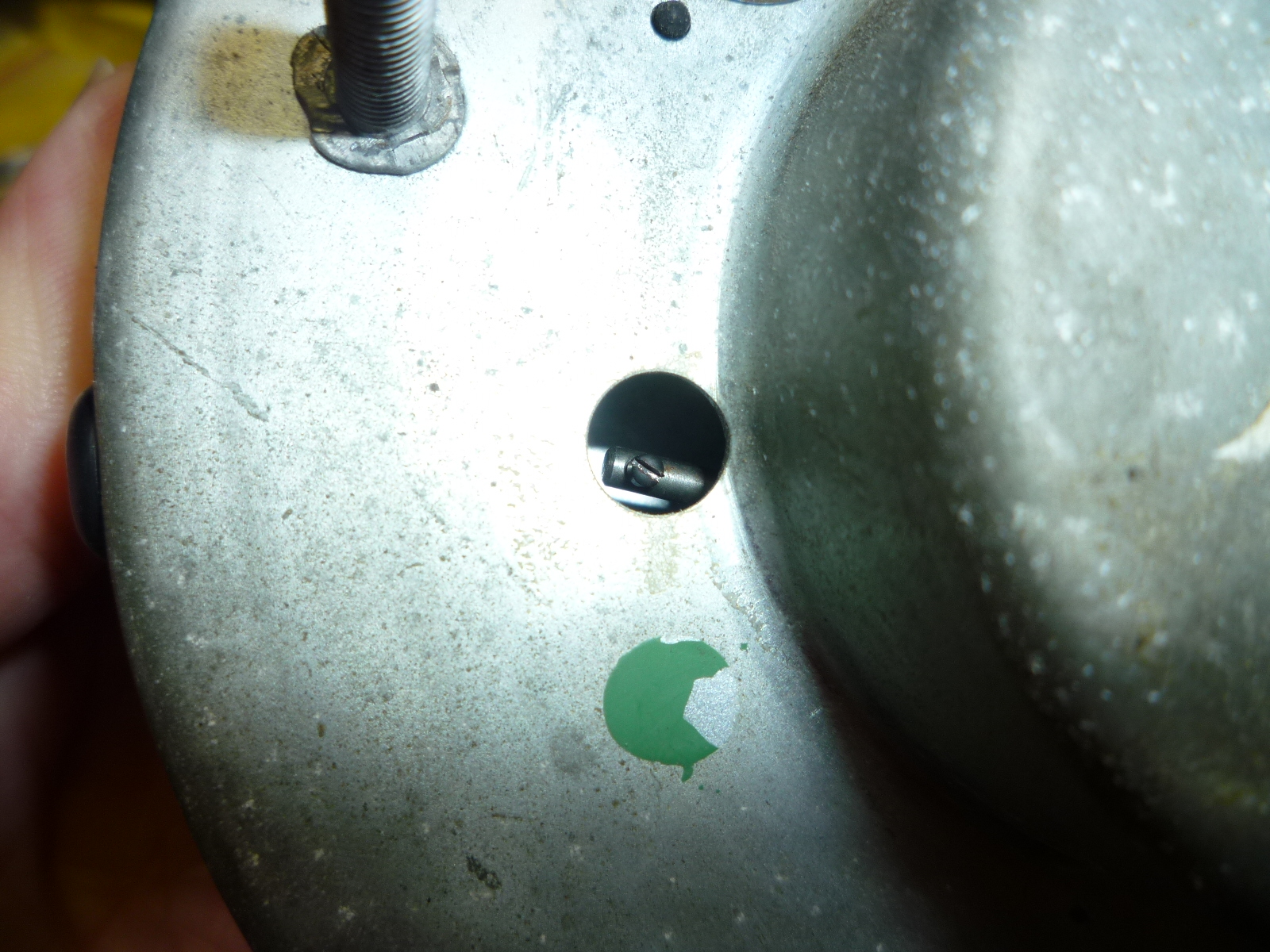
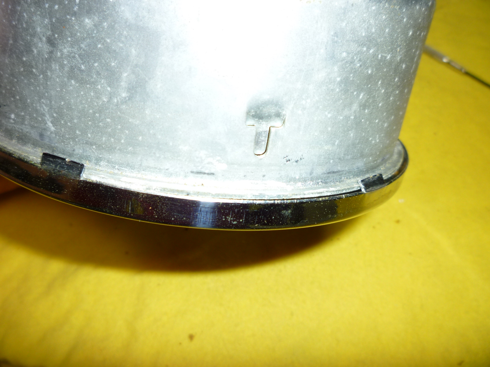
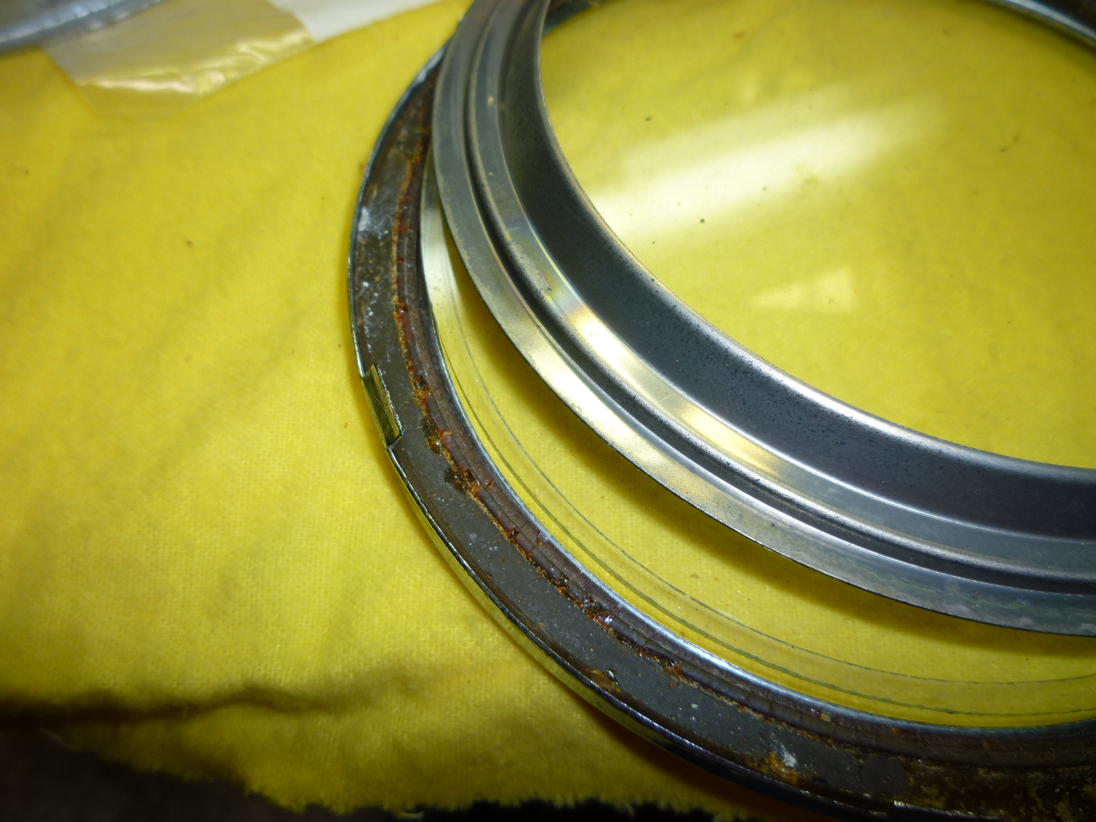
As I unscrewed it, I turned the speedometer on its back so the screw would drop out the hole. Well, it ended up inside the speedometer despite my efforts. The next time, I'll stick a magnet to the side of the jeweler's screwdriver so the tip is magnetized. I shook the speedometer around trying to get the screw near a hole, but failed. So had to disassemble the speedometer. The big issue is removing the bezel without breaking off a tab or damaging the bezel. To start, I use a small bladed screwdriver to pry up and out on a single tab. I've found that having some support (thumb) on the outside of the bezel right at the tab will help direct the force into lifting the tab rather than bending the bezel outward. Once a tab is lifted slightly, I use a small pair of pliers that have a flat blade about 1/4" wide. These can then fit under the tab and let you straighten it more precisely. I do not completely straighten them, but end up with a couple on one side slightly open and the others on the far side at about a 45° angle. Then I carefully pry by each tab, popping the tab and bezel off the instrument surround. After four (of the six) were done on the speedometer, the bezel will slide off on the side with the tabs that were only slightly opened. Here are a couple of pictures to give you an idea of what I'm talking about.
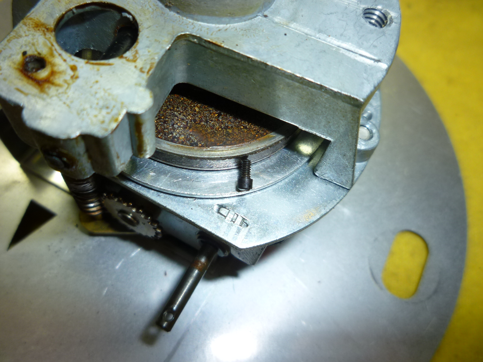
Once the speedometer was apart, I found the screw stuck to the magnet that is part of the speedometer. The speedometer works by having the cable spin a magnet that causes the speedometer needle to move relative to the speed the cable is spinning. No wonder I couldn't shake the screw out.
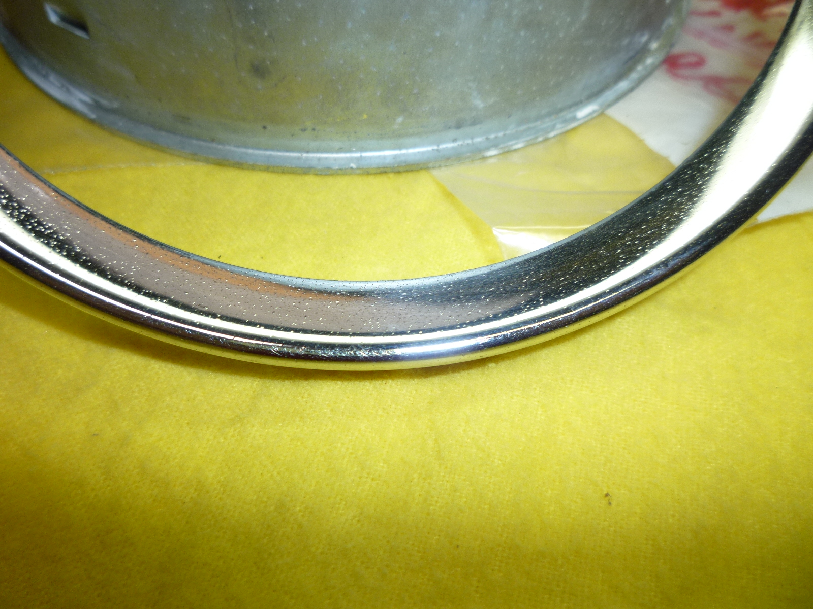
I polished the bezel and looked at the chrome. It was good, but not great, with minor pitting (you can see speckles in the picture) that would just get worse. Since I was amassing parts for chroming, I just added it to the bunch. However, I know that I'll probably have to do the bezel on the tachometer to match now and take a careful look at the other instruments.
I also took the opportunity to replace the grommet that protects the flexible tail from the speedometer housing as the old one was in pieces inside the housing.
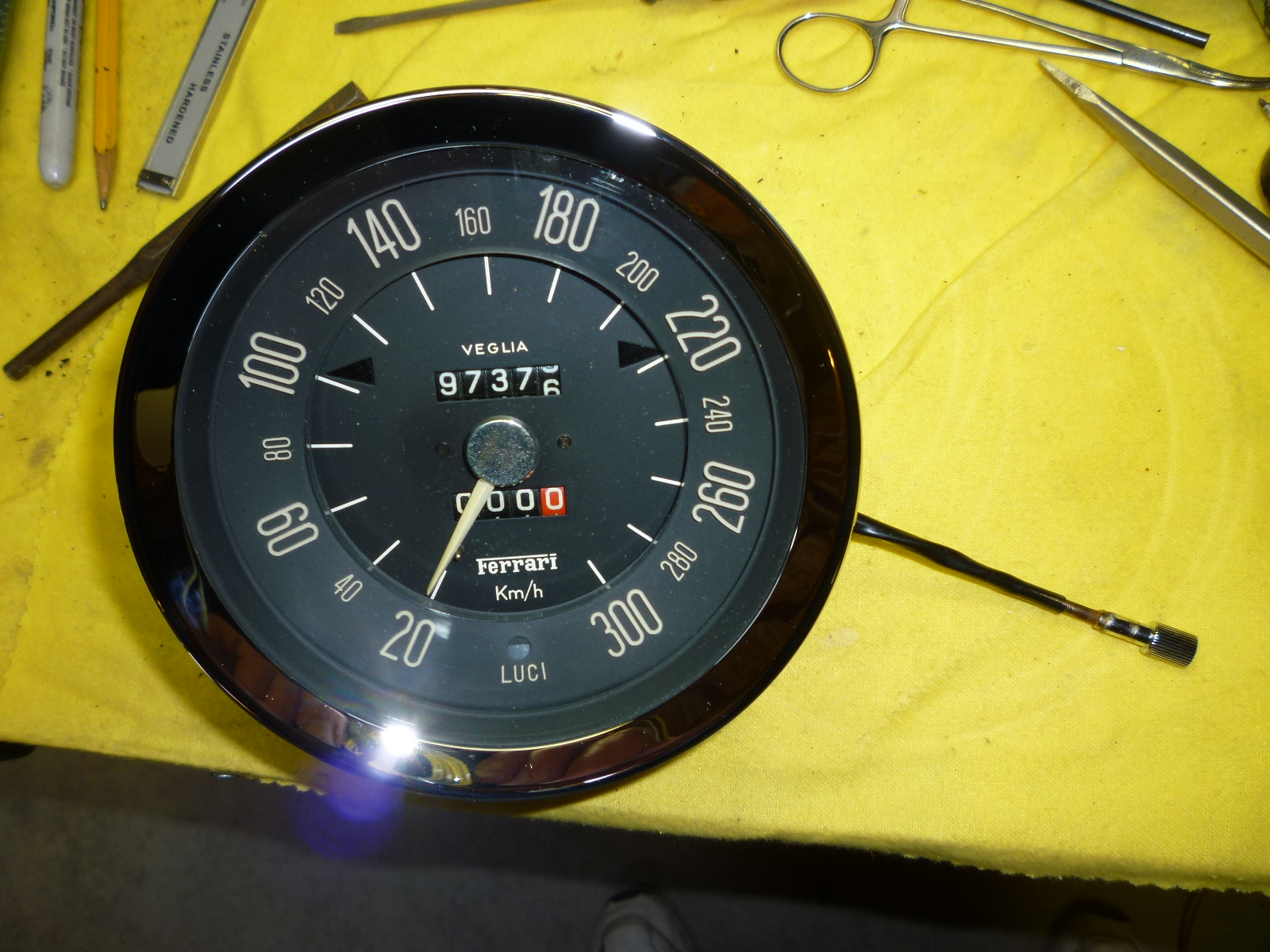
When I got the two tails back from chroming, it was time to assemble the speedometer. At first I tried to put the tail through the housing, onto the reset shaft and then install the whole thing into the housing. Well, that turned out not to work. You have to install the speedometer, twist it slightly so the reset shaft lines up with the grommet hole. Then you can slide the reset tail onto the shaft. Once that is done, align the speedometer with the screw holes in the housing and tighten it down. Now you have the opportunity to drop the screw inside the speedometer just as I did when I took it apart. This time I was smarter and taped the tiny screw onto the jeweler's screwdriver. After carefully aligning the holes in the reset tail with the one in the shaft, the screw fit in and started easily. I'm glad I got that done without having the screw come loose. I did do this before putting the bezel back on, so if the screw had dropped, it would have been easy to find. Here are the speedometer and clock and their newly chromed tails.