Wiring
I needed to clean and refinish the metal coil wiring tubes (like BX electrical cable) that run around the engine compartment. This needs to be finished before the engine is installed because it would be in the way. To do this well, I needed to wire brush the surfaces. At first I was planning on putting the grinder with a wire brush inside the engine compartment, stand and all. That way most of the wire tubing could be done in place and I could use the Dremel on the few inches that wouldn't reach. However, the stand was too large to fit.
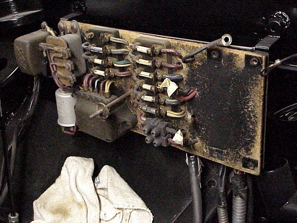
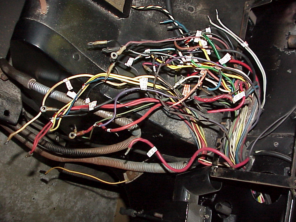
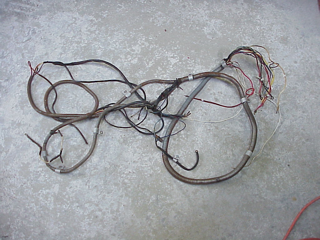
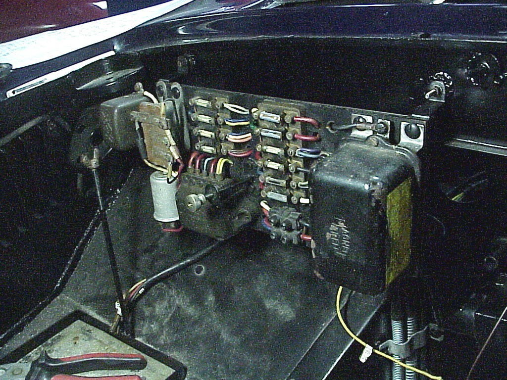
I has already decided to replace the hardboard backing for the fuse panel. In order to do this, all of the wiring has to come loose anyway. So that would solve the tube problem since I could remove them and do it away from the car. The starting point looks like this:
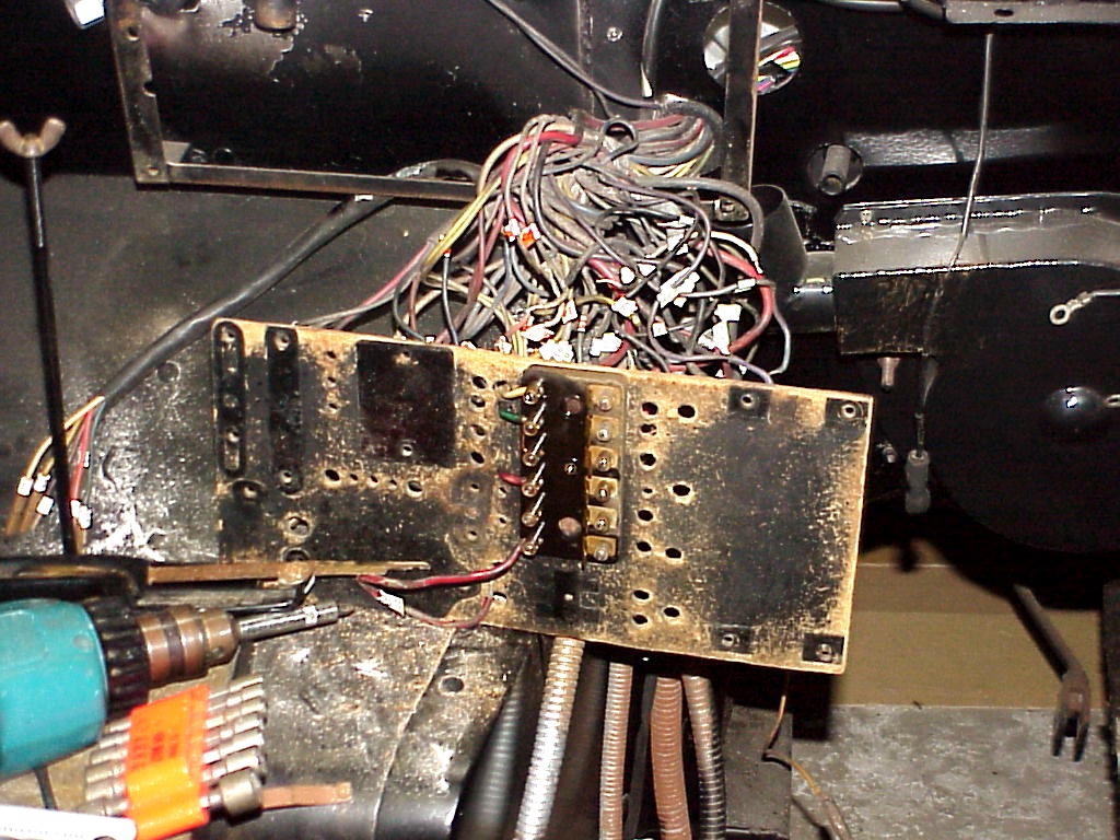
It took quite a while, but everything came apart except for four of the fuse end screws. I ended up cutting the wires. Once the fuse block was removed, I put it in a vise and have penetrating oil around the screw so hopefully they will be removable in a few days. While I was undoing everything, I was noting the color and where each wire attached. At the same time, I put a numbered wire marker on the wire far enough back so it would be behind the panel. This way I know exactly which wire goes on which terminal.
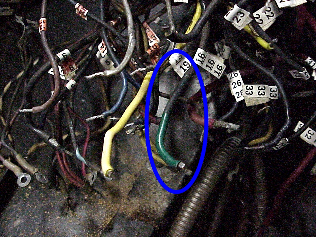
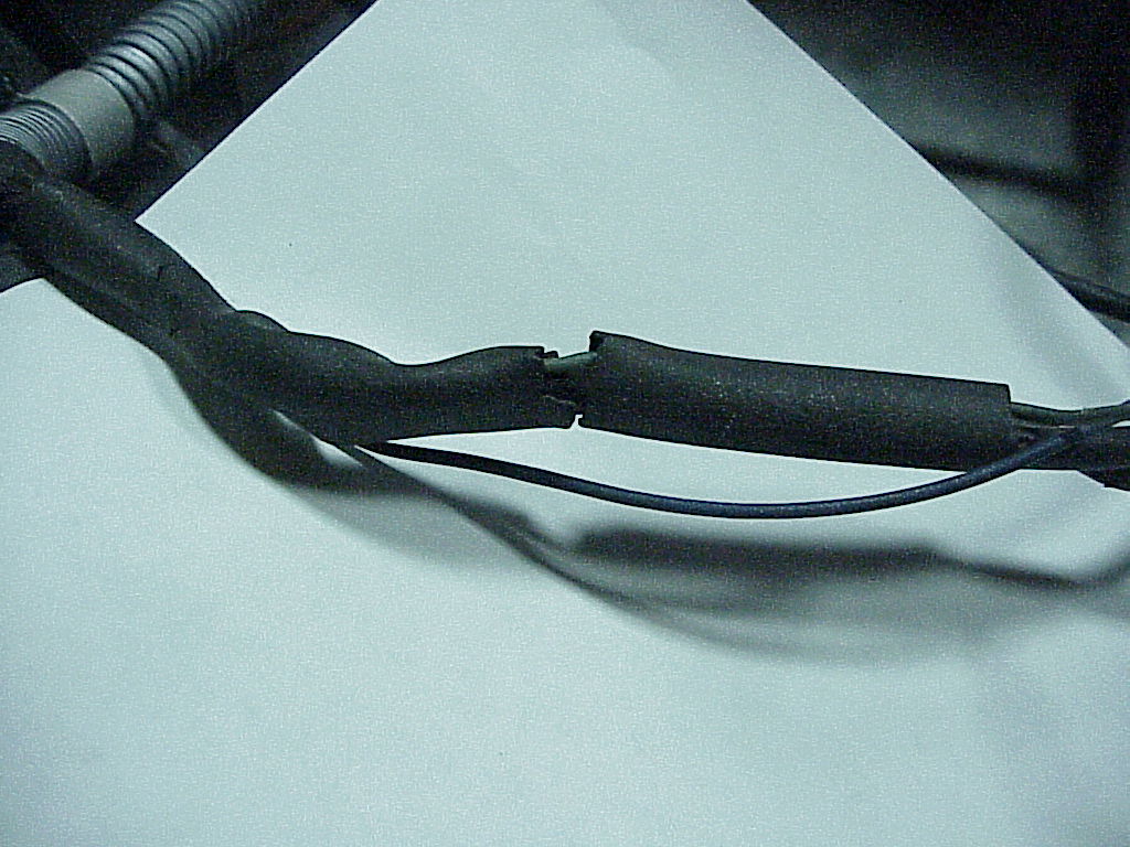
After the panel was removed, I cleaned all of the wires so I could see the true color. A couple of black ones ended up gray and brown after the gunk and overspray was removed. Here you can see a partially cleaned green wire and the final result.
 |
 |
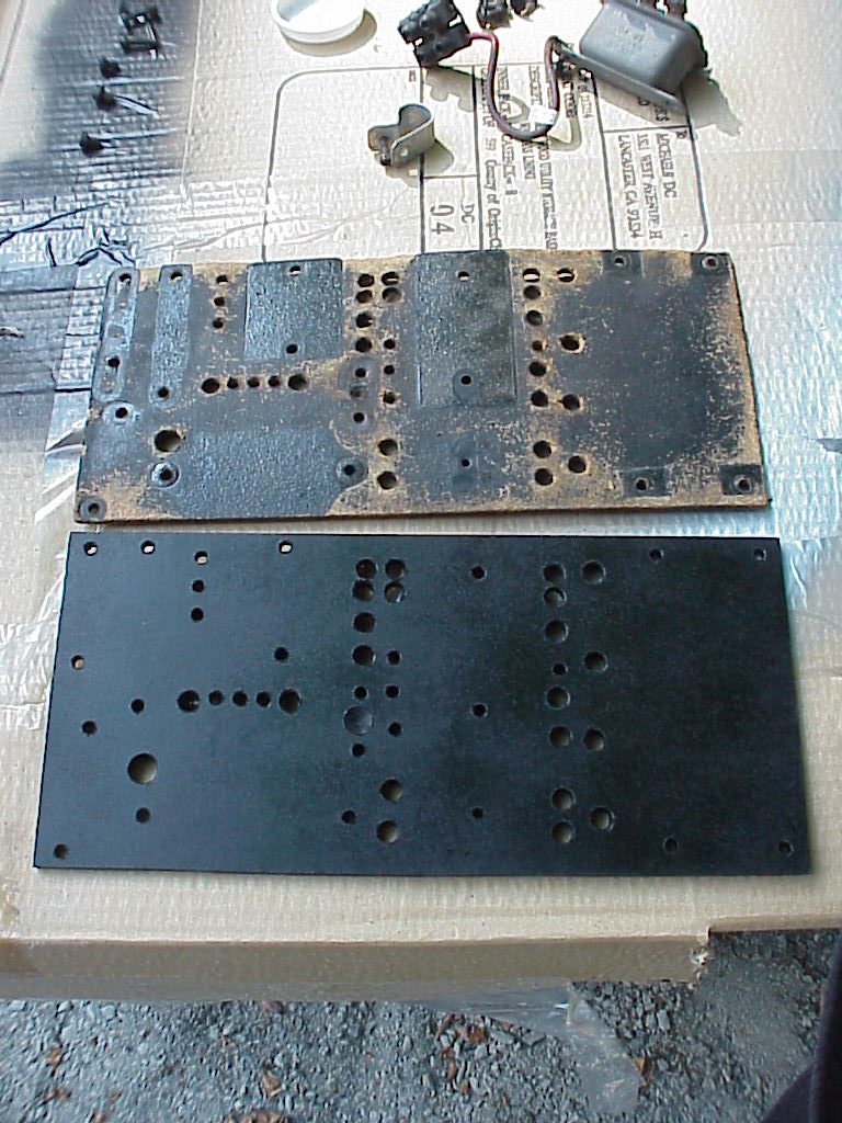
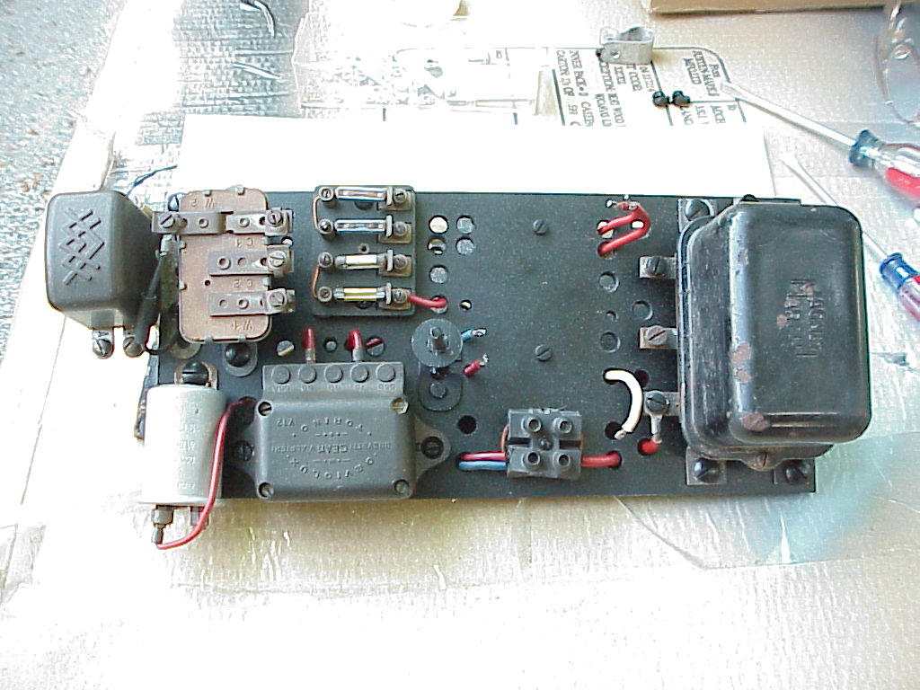
The next step was to make a new hardboard back. I went to two home stores to buy the hardboard, but in the smaller sizes, both sides were smooth. The original was smooth on the face and waffled on the back. So I ended up buying a 4'x8' sheet of the right kind in order to have a 7"x11" piece. There were plenty of holes to drill in four different sizes. Here's the original and the new on on the left. The right picture has everything mounted except for the large fuse block. It's still soaking in order to free up the last screw. At least I got 3 of the 4 freed up.
 |
 |
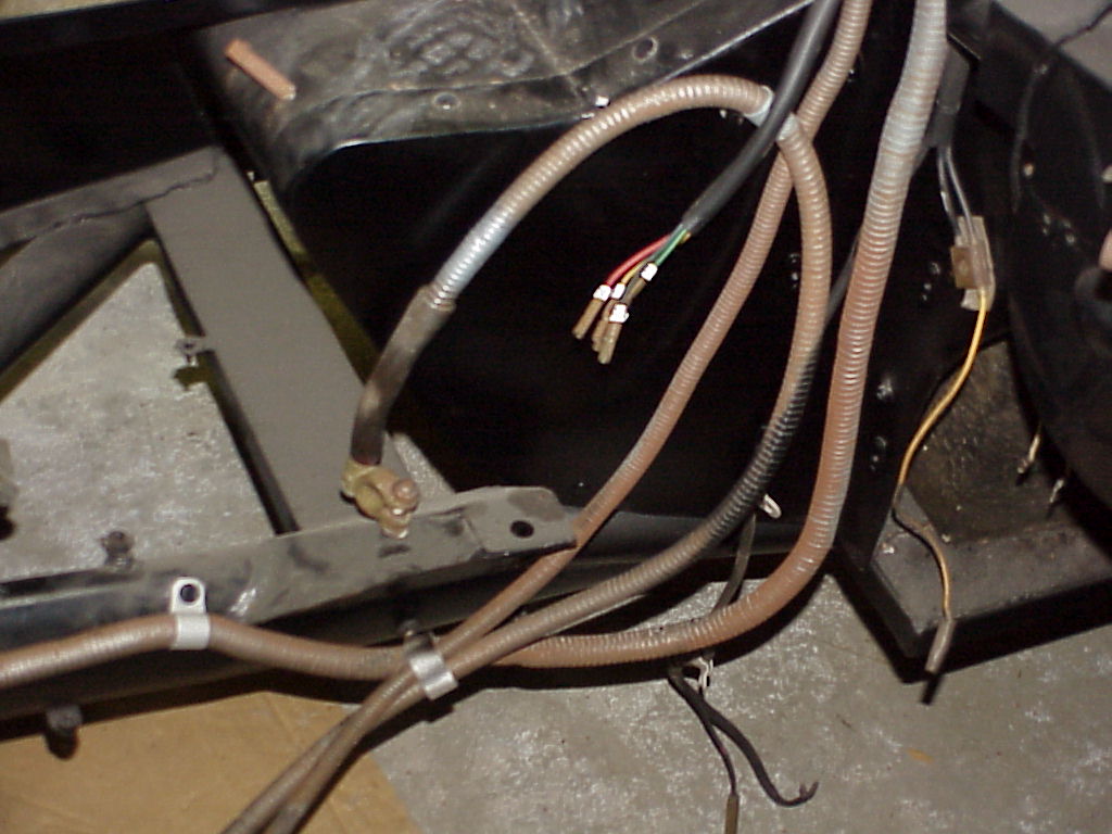
I also needed to clean and paint the wire covers which was the reason I started this project. I was able to remove two of the four wire tubes pretty easily. The other two will have to wait for another day. I used the wire wheel to clean off the old paint, rust and crud. Then I painted them with Eastwood clear zinc paint. You can see them in the background along with some of the fuse panel hardware I was painting at the same time.
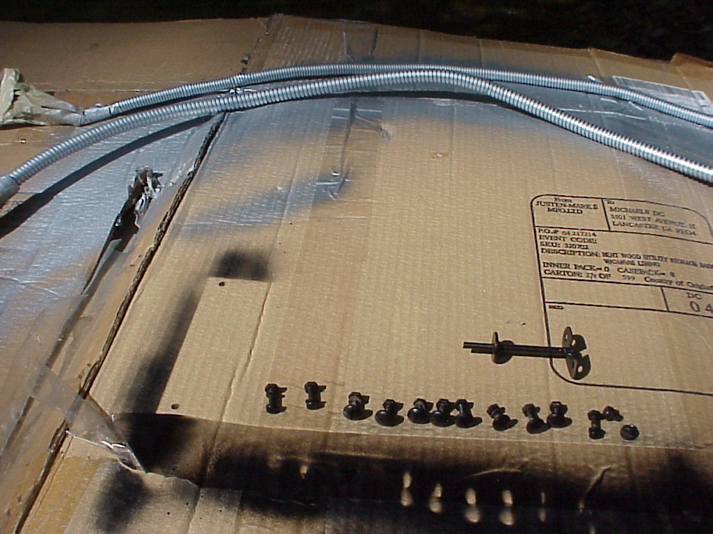
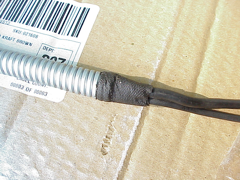
At the end of each tube, the wires are wrapped with the old style friction tape covering. This was to prevent the wire from fraying against the sharp ends of the coil tubing. When I was at the home store, I found a roll so I was able to finish the ends like they were originally.
The last two wire bundles will be harder. The one in the engine compartment has two wires that go through the firewall into the passenger compartment. I have to undo the harness inside in order to pull these free so I can remove the bundle from the car. The other goes down under the car and then towards the back. That one will wait until I have the car on the lift.
I removed the heater box and fan so I could take apart the wire bundle. When I traced the two wires, I found that they went to a soldered connector with two other wires each. It turns out these wires are the left and right turn signals. One wire for each side goes forward, one to the indicator lamp and the other to the rear. The ones leading to the rear end up in the other wire tube that I still have to remove. It didn't look possible to remove it and keep the two wires in one piece, so I ended up cutting them. Once they were cut, I got the whole bundle out in one piece.
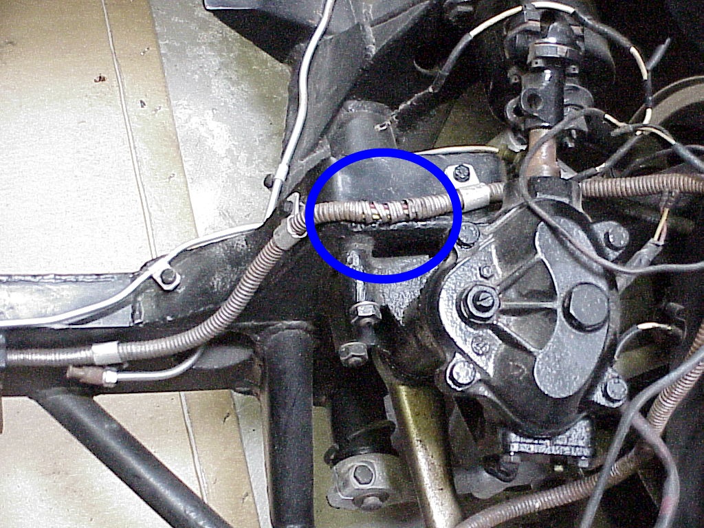
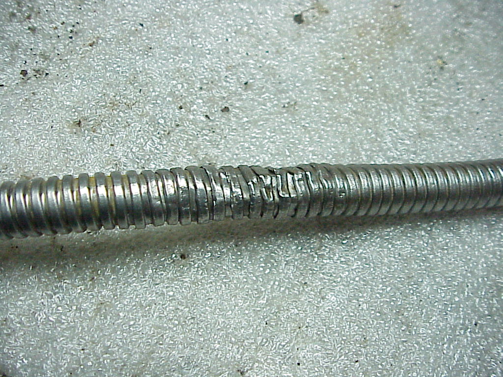
After wire brushing each of the sections, I took some time to try and round out the places where there were kinks. One place had been smashed enough that several of the coils were no longer interlocked. I spent quite a bit of time getting these back so they locked together. You can see the bad spot circled in the left picture and my completed repair on the right. Not perfect, but a lot better than having the open coils.
 |
 |
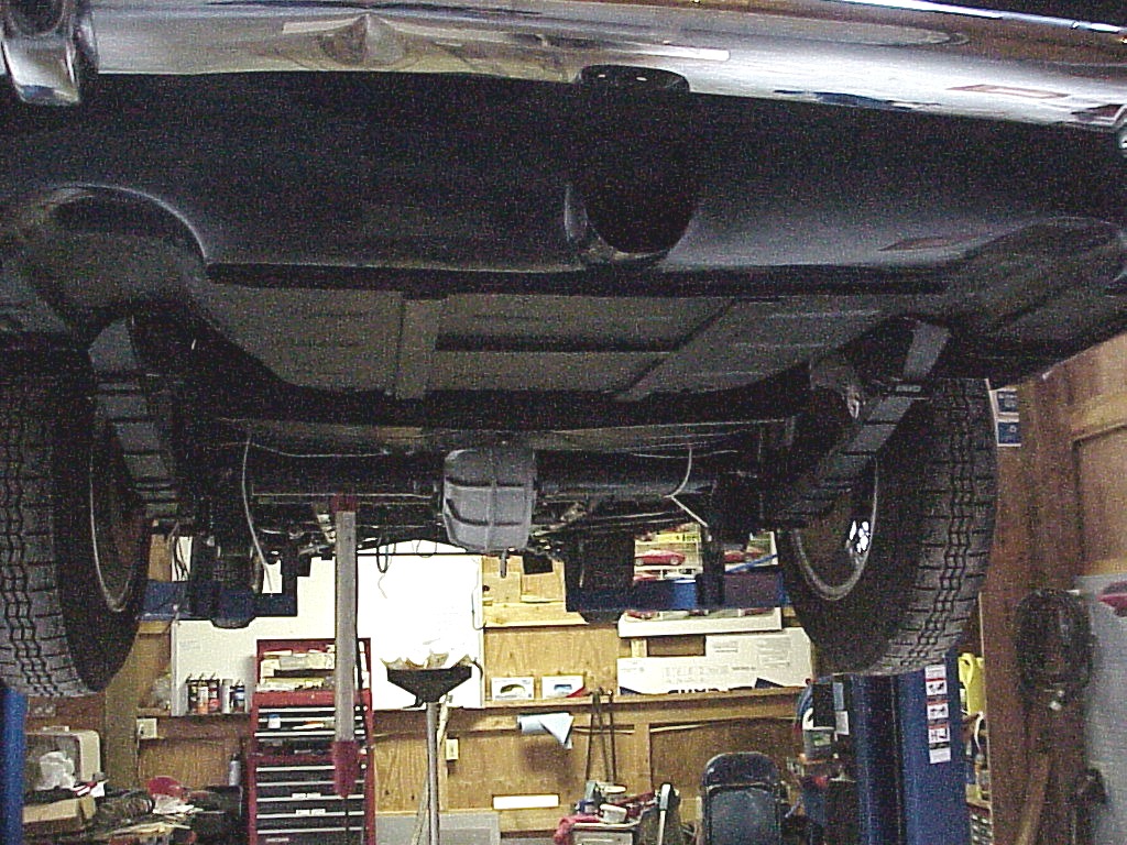
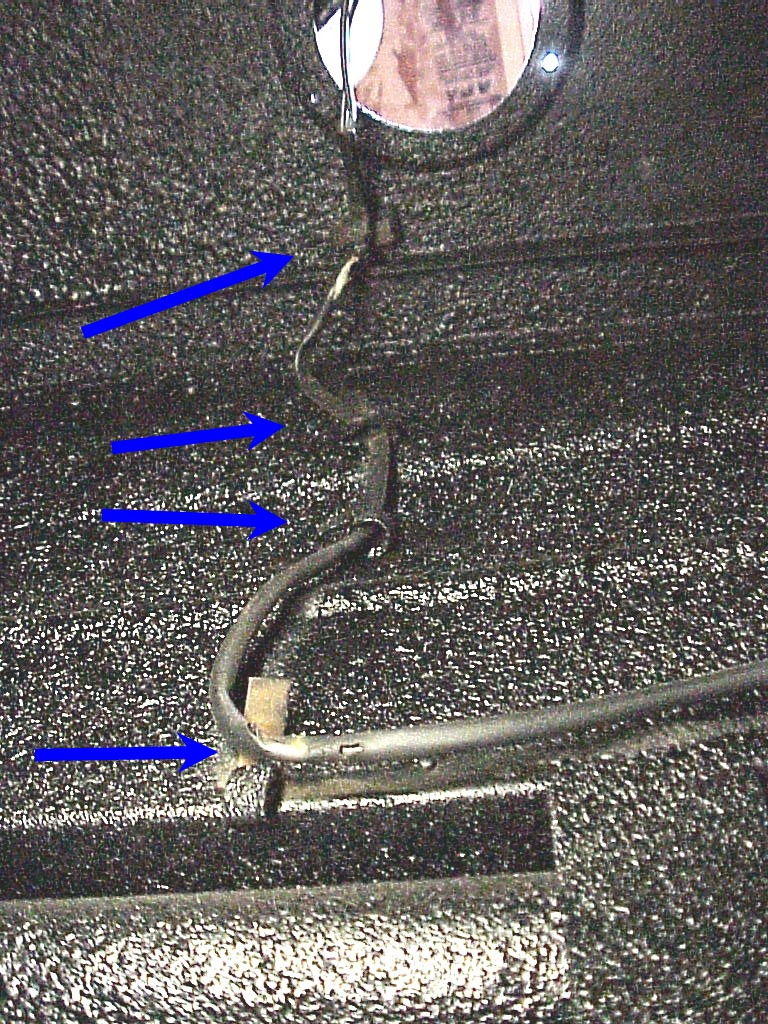
I finally got the PF coupe put on the lift. One piece of bad news. There's a dent on the underside of the rear bumper that I hadn't noticed before. I was able to remove the fuel tank and get to the clips holding the last wire bundle in place. It turns out that Pininfarina worked overtime on these clips. There were four of them buried between the fuel tank and the panel for the trunk.
|
|
|
Now that the last wire bundle was free, I figured out the last parts of the wiring diagram I've been making. Since there never was an owner's manual published for the PF coupe, no wiring diagram exists. The one for the inside plug cars didn't have a lot of the newer features (like the overdrive) and the one for the GTE had too many, including the change to 12 fuses rather than 10.

With this diagram, I don't have to worry about where all of the disconnected wires to the dash go. I do know that you don't want to be working under the dash without disconnecting the battery. Some of the switches have unfused power going to them. Grounding one of these through a ring or watch would lead to lots of sparks and probably a severe burn.
It's been a while, but I just put in the fuse panel. Since I had labeled the wires as I removed them, most were no problem. However, two had lost their numbers, so it took a little tracing to figure out where they went. I had one extra wire with a number that didn't make sense. I finally figured out that it was supposed to go inside the car as it led to the fog lights. Once inside, the F switch had the matching number on it.
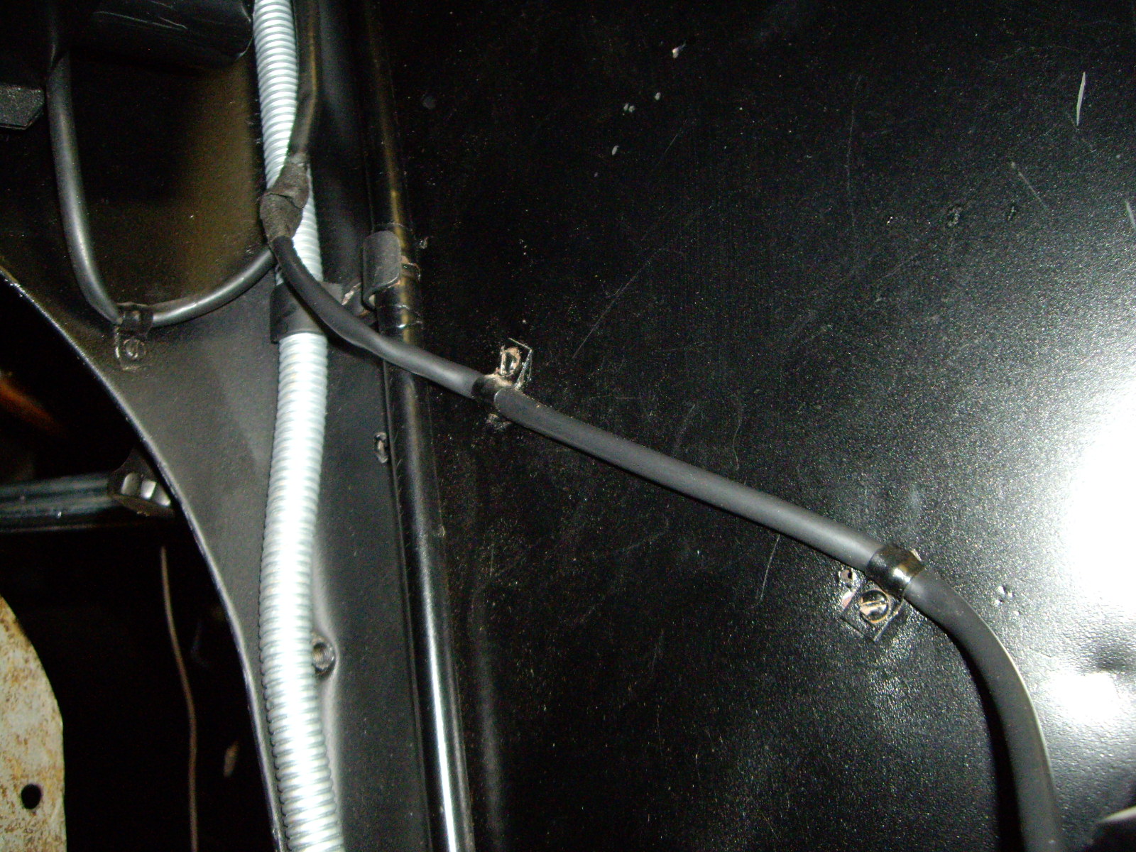
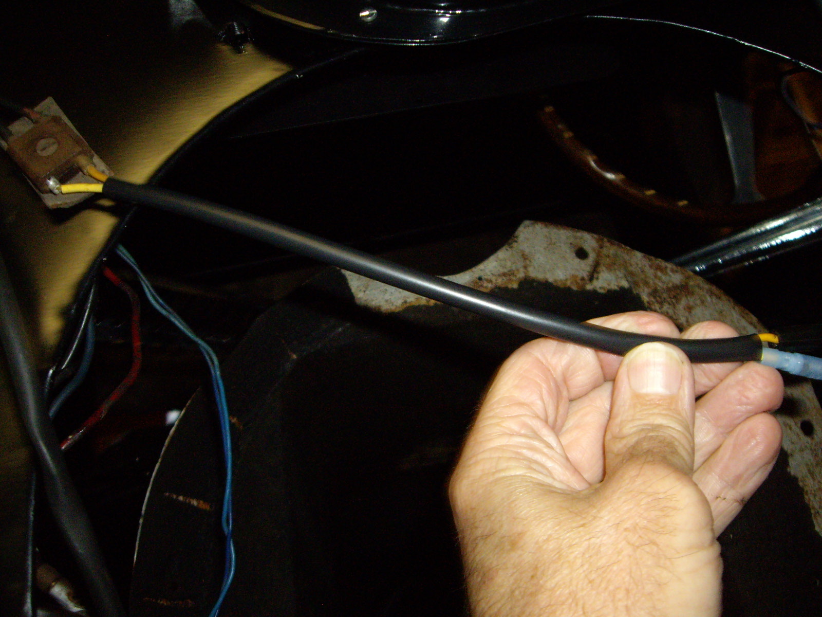
I also got a bunch of the plastic tubing that the wiring runs through. So I've been replacing the original as needed. Some is cracked, some was ruined by the sand blasting that was done on the frame and others are just so stiff to be unusable. The major issue is that the tubing was originally installed before the connector ends were put on. So in some cases, I have to unsolder and remove the end, install the tubing and then re-solder the original end back on. Not difficult, but it takes about 15 minutes per end.
 |
 |
Some of the wiring was cut or the connectors cut off. So I'm having to fix these issues as I continue to get the wiring in shape.
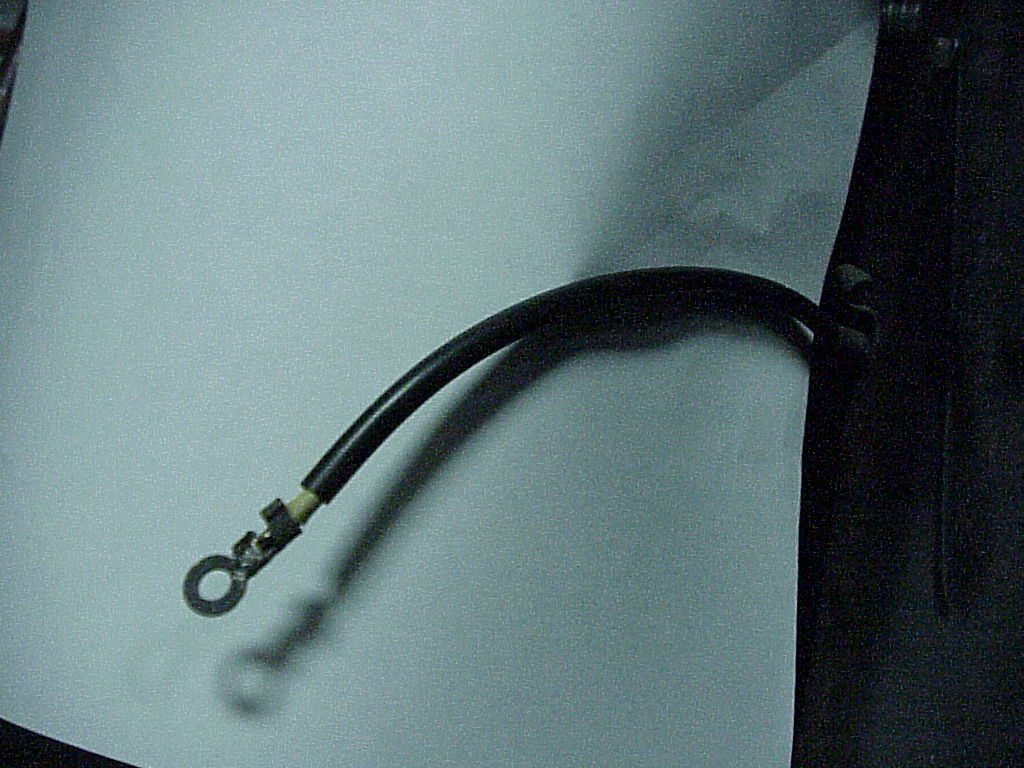
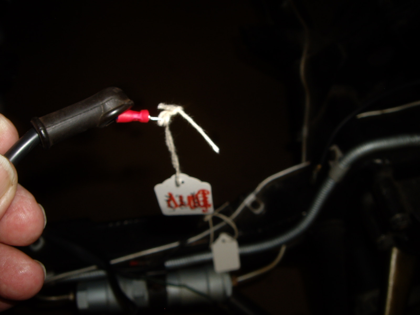
As usual, putting everything back together isn't as easy as it could be. There were some wires terminating near the right front of where the engine would be. I figured out that three of them went to the generator. The fourth confounded me. I first thought that it would be for the sender for the temperature gauge, but the wire terminated at a fuse, not inside where the gauge would be. This is a case that if the engine were in the car, the answer would have been obvious. It turns out that it goes to the thermostat for the magnetic fan clutch. So I put a new sleeve, a rubber boot, the proper circle end and a tag so I won't have to figure it out again.
Next I wanted to find the wire for the temperature sensor. One of the
problems on working on the PF Coupe is the lack of exploded view parts
books. Since I don't have the engine together, nor did I take it
apart, some things aren't apparent. I asked my friend who also owns a
PF Coupe where his sender is. He came back saying that it screws into
a pipe that connects both heads at the rear and then goes forward on the
driver's side. I found my matching part and yes there was a tapped
place for the sender. Digging around through plastic bags came up with
sender (and the fan clutch thermostat). The oil sender (identical part
to the water sender) was still on the sump and both had their bullet socket
loose. So I cleaned up both and soldered the bullet socket to solve it
being loose. Dug out new copper washers and put all of the parts back
in a plastic bag for later installation. Now that I know that both
senders were at the rear of the engine, I found the pair of wires coming
through the firewall. The only thing I had to do with them was to
re-install them under the clips on the firewall and foot well. I also
labeled them for when the engine gets installed. I also added a
missing wire that goes to the O/D lockout
switch on the transmission.
 |
 |
The next step in the wiring was to find and label the wire ends for the dash instruments and switches.