Al's Locks
Al Pezzella (8917) wanted to get his locks chromed. He took them off the car and then to a local locksmith to get them taken apart so he could take the appropriate pieces to a plating place. Evidently, once the locksmith found out that these were somewhat irreplaceable, he declined to work on them.
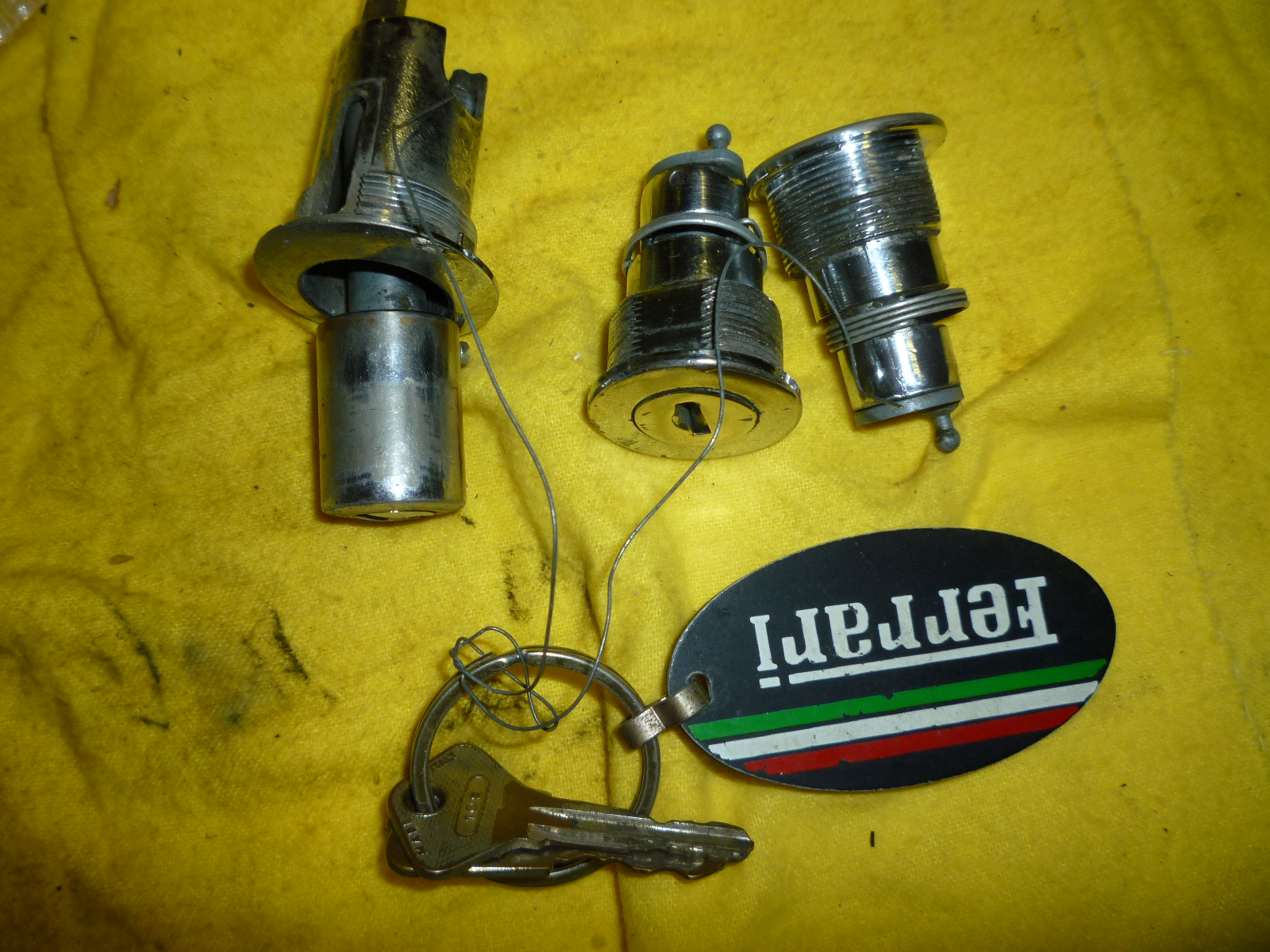
I offered to do this for Al and he took me up on it. He sent me his two door locks and the trunk lock along with keys that worked the locks. It's always easier having the keys when taking locks apart.
When I did my 330 GT locks in the early 80s, I didn't take any pictures as this was in the age of film cameras and I wasn't going to waste film on some old locks for pictures I would never need.
This time, I did take some pictures and here they are.
I started with the door locks.
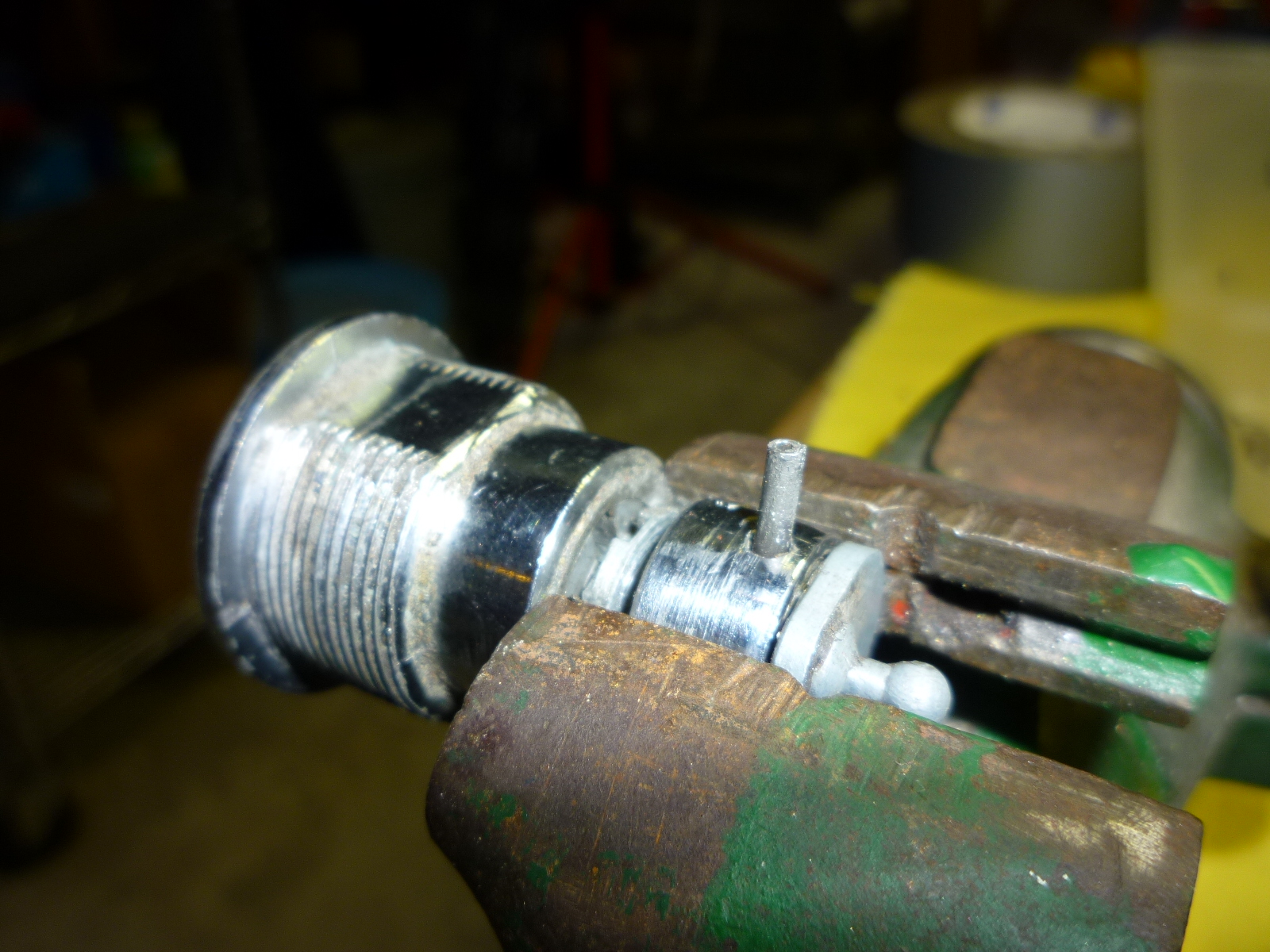
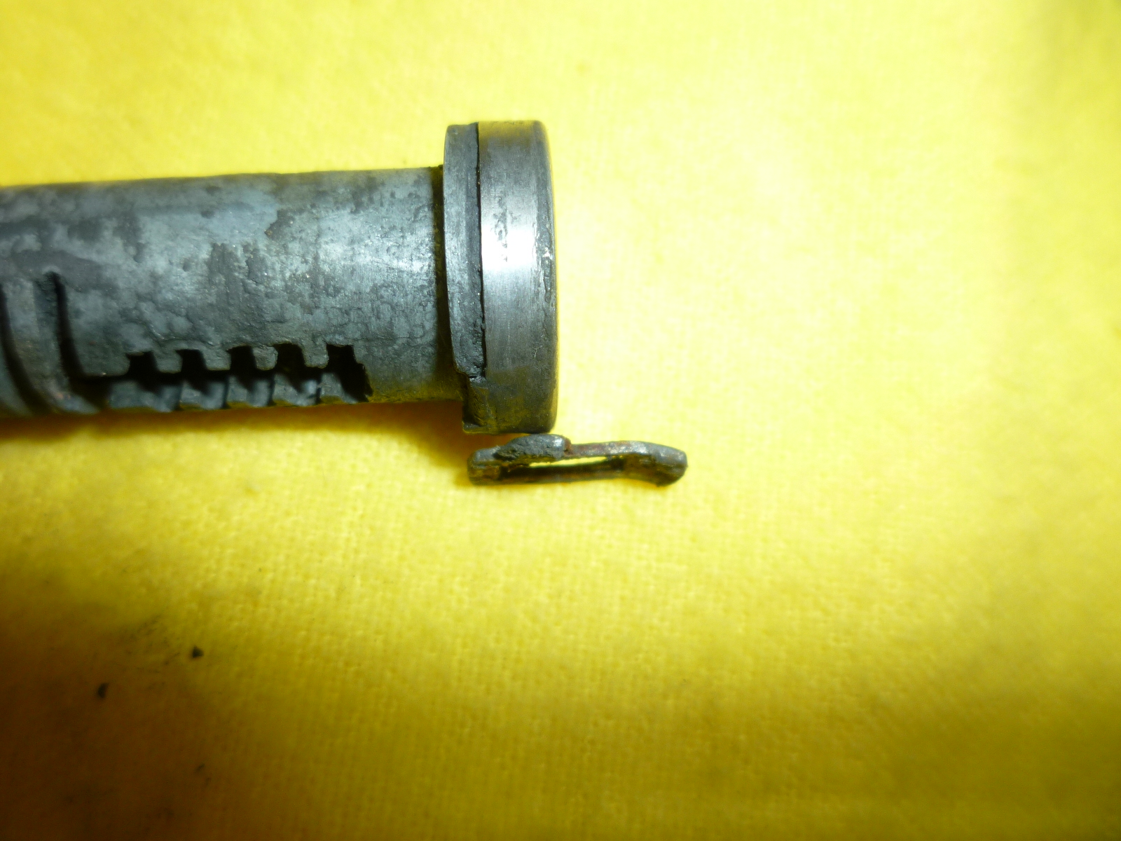
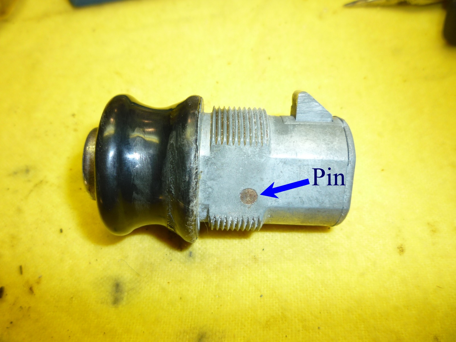
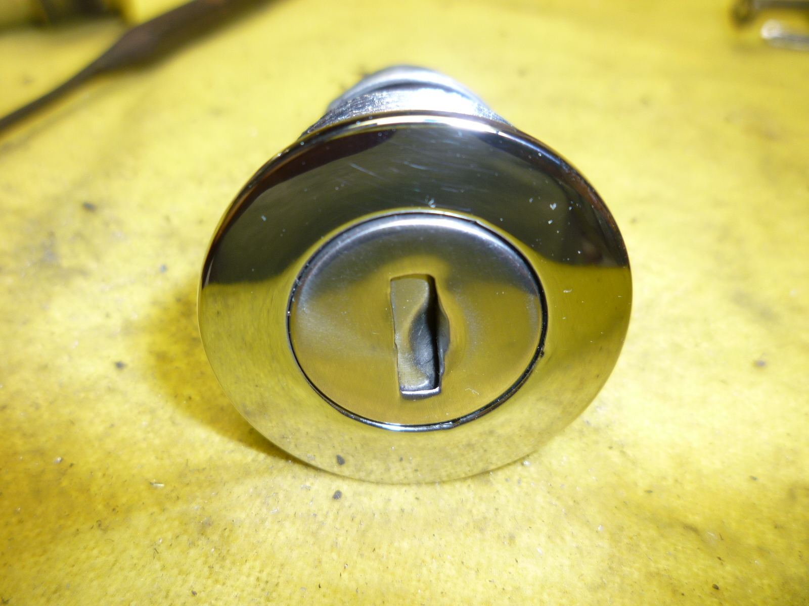
The ball on the back fits into a socket that is attached to the lock knob and rod in the door panel. It can rotate 1/4 turn each way without moving the lock. This allows the door to be locked and unlocked from the inside with the pull knob. When the key is rotated on one direction the ball pushes the rod up and the other direction pulls it down thus mimicking the action of the knob on the inside. The socket tail assembly is attached to the back of the plug with a roll pin. The pin is accessed though a hole in each side of the cylinder when lined up properly. Here you can see the pin almost completely driven out using a small pin punch. I had already removed the spring which centers the lock when you release the key.
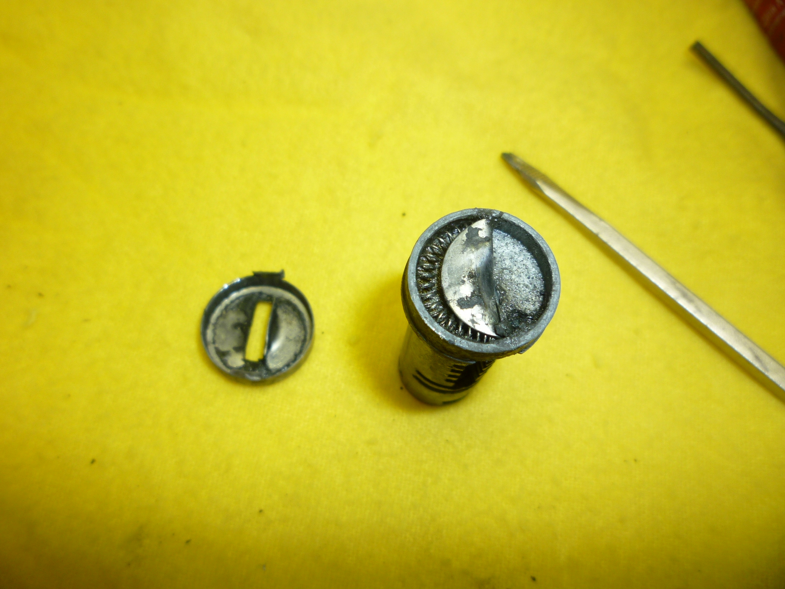
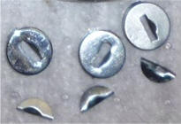
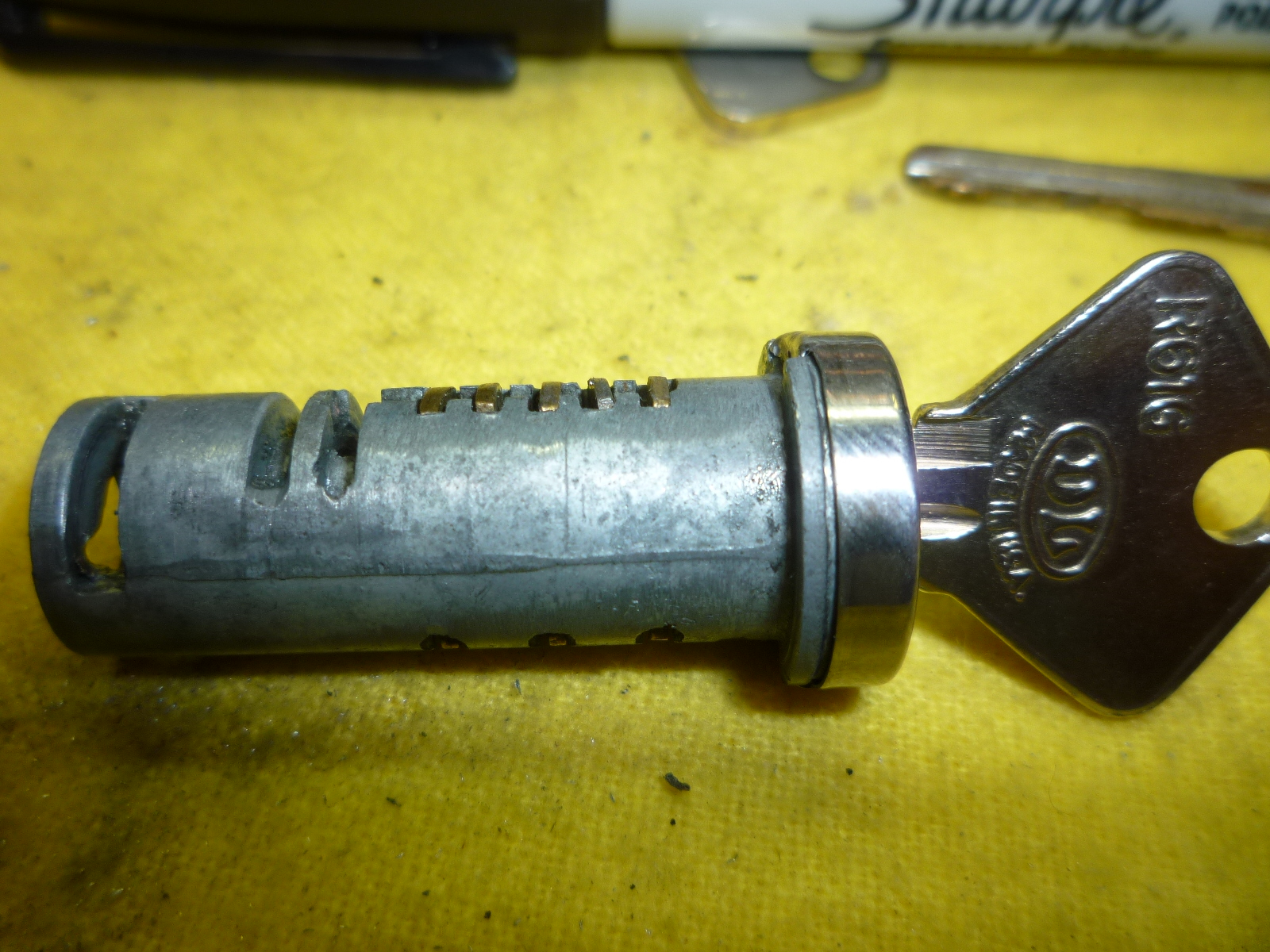
Once the spring and pin are removed, nothing holds the plug in the cylinder. And as this is a wafer lock, the cylinder just slides out the front without needing a key or shimming the lock. The only trick is to be careful so the wafers don't pop out and get lost or mixed up. On one of Al's locks, a wafer was bent and jammed in the slot. I was surprised that key would go past the jammed wafer, but it did. I had to tap out the wafer and then straighten it. Here's the bent wafer next to the cylinder.
There is a little door that covers the keyway to prevent dirt and water from getting into the lock. I never knew how these worked as I have never taken mine fully apart. There is a semi-circular spring sitting in 1/2 of the cylinder front. Each end of the spring sits against tabs of the little door. When the key goes it, it pushes the door to the side against each end of the spring. When the key is removed the spring pushes the door back to cover the keyway.
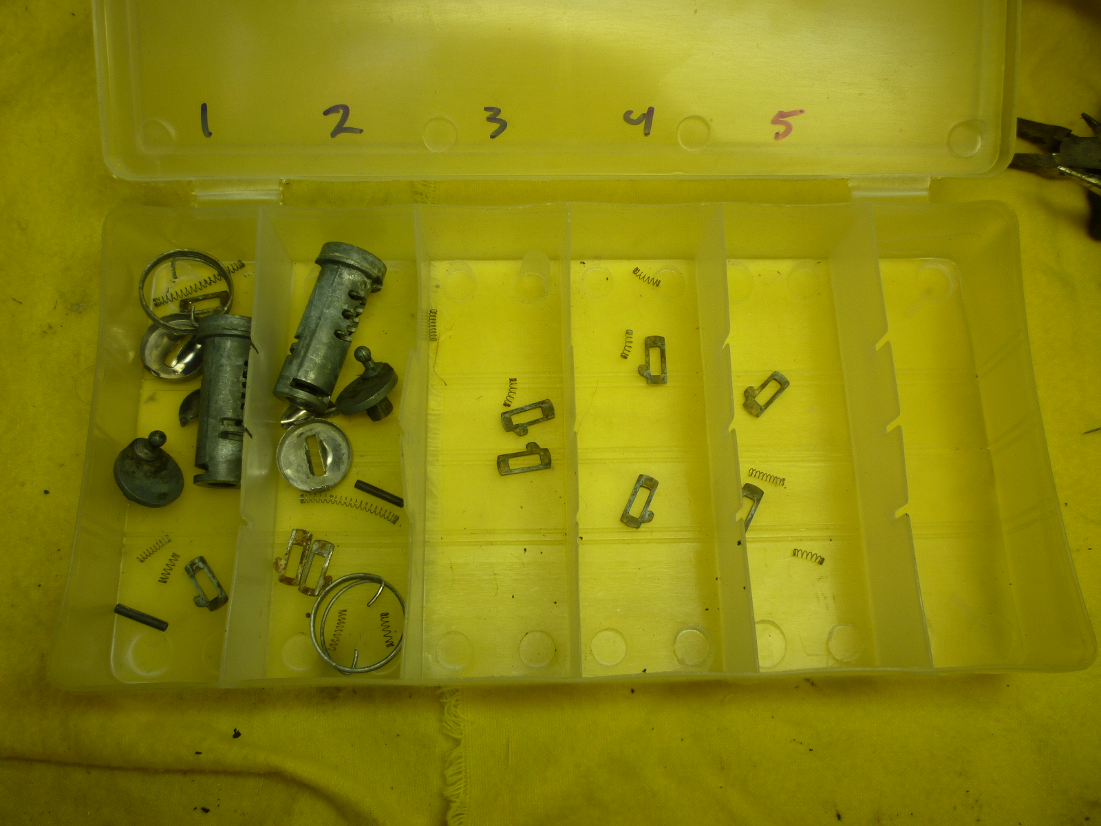
Originally I though that the little door and covering bezel were stainless steel, but it turns out that they are stamped steel that is chrome plated. More items to get chromed. Here are all of the lock parts sorted into a tray so the correct wafers go back in the right slots to fit the existing key.
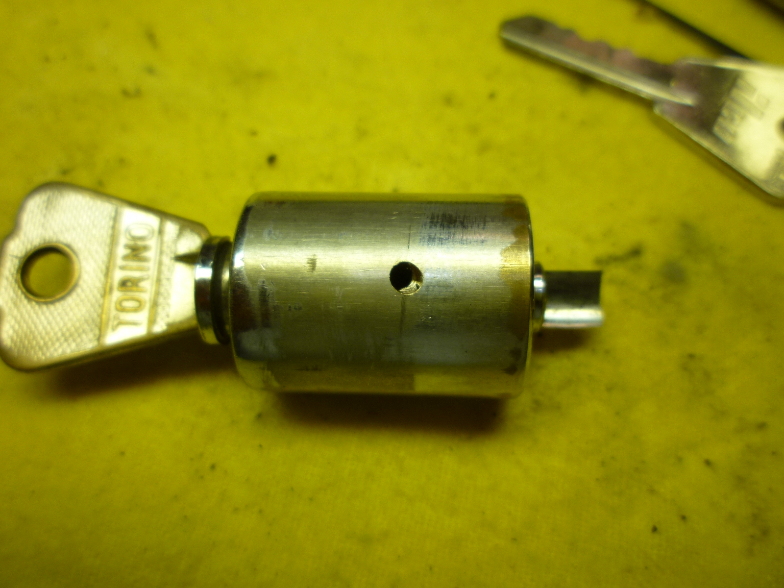
Next I tackled the trunk lock. I can't remember if I took mine apart 25+ years ago, but if I did, I was quite lucky to not make the mistake I made on Al's. To start, a brass pin gets driven out to remove the tail piece (that pushes on the latch mechanism when the button is depressed). Then there is another pin that goes through the body into a slot in the cylinder. That slot only goes 1/2 the way around and stops the cylinder in either the locked or unlocked position. In the locked position, the cylinder fits against a projection in the barrel that prevents the button from being depressed. In the unlocked position, the projection is out of the way and the button can be pushed down.
Once the tail piece is removed, the cylinder can be removed with the key inserted to align the pins correctly. I did this and pulled the plug forward (it comes out the front of the lock). I didn't shim the pins and use a follower as I was going to remove all of the upper springs and pins since the barrel had to go to be chromed. The only problem is the slot for the 1/2 turn stop. The last upper pin dropped into that slot and prevented the cylinder from coming any further out. In addition, I had the key in the middle between locked and unlocked, so both sets of upper pins dropped in the slot, one at each end. This lock has 2 sets of uppers, so the key can be removed in either the locked or unlocked position. So now I was stuck, the key was in the lock and couldn't be removed as it was half way between locked and unlocked. The upper pins were at both ends of the slot so the lock wouldn't turn either direction. After a while, I figured out what had happened.
My trunk lock also to be chromed, so I decided to remove it and take it apart, being more careful. This time, I shimmed both sets of upper pins and used a follower to prevent any upper pins from dropping into the slot. Here you can see the slot at the bottom under the fourth pin location in the plug on the left.
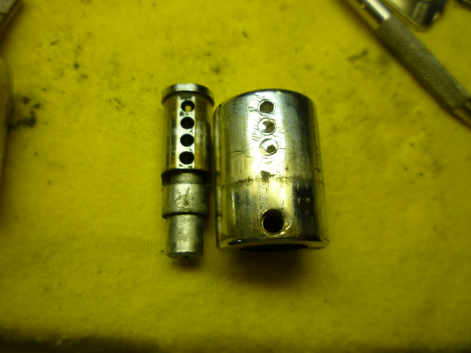
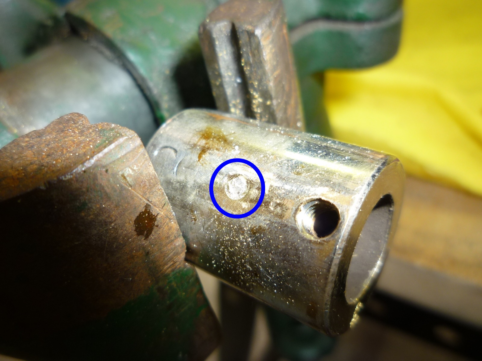
Once I confirmed that I understood what was keeping Al's lock together, there was only one solution. I had to drill out the cap covering the upper hole for the fourth pin (the one that dropped into the slot). Once that was done, I fished out the spring and the upper pin could be knocked out of the slot. Now the lock would rotate the 1/2 turn until the other upper pin hit the ends of the slot. So I had to drill the other side of the cylinder to remove the other upper spring. However, it was obvious where to drill on the one side as the original drilled holes for the pins were capped (you can see the indentations in the picture above). On the other side, they didn't drill completely through as they didn't need to. I had to figure out where to drill on that side by measuring from one side to the other. Once that was done, I drilled, being careful to go just deep enough and not have the spring get caught up in the drill bit. My measurements were off a few thousands, which actually worked out as the spring couldn't pop out the partial hole, but I was able to fish it out. If you look carefully (perhaps click on the picture to see the large version), you can see the overlap of the holes on the left with the plug left un-drilled on the right side of the new hole.
Once I fished out that spring and knocked the upper pin back in the cylinder, I shimmed both sets of pins and the plug came out just like mine did. Maybe there was a reason that Al's locksmith decided that he didn't want to do it! After I got the lock apart, I made a couple of little brass caps and soldered them into the holes that I had to drill.
After cleaning everything, the last thing I did was to use heat shrink to cover the plugs and threads on the cylinders. After my experience with the PF coupe locks where thickness of the chrome plating was enough to make things not fit back together, I hope that the heat shrink will prevent the plating from occurring where I don't want it. Here's all of the parts ready to be chromed.
Next up will be the re-assembly once the chroming is complete.
One of the things that I noticed was that one of the door locks had some material missing. It looks like it was hit with a sander or grinder.
I asked Al if he wanted to try and get that fixed. It turns out that he has two extra door locks, so he sent those out. That way, I'll just use the best housing, get it chromed and put the other innards into it.
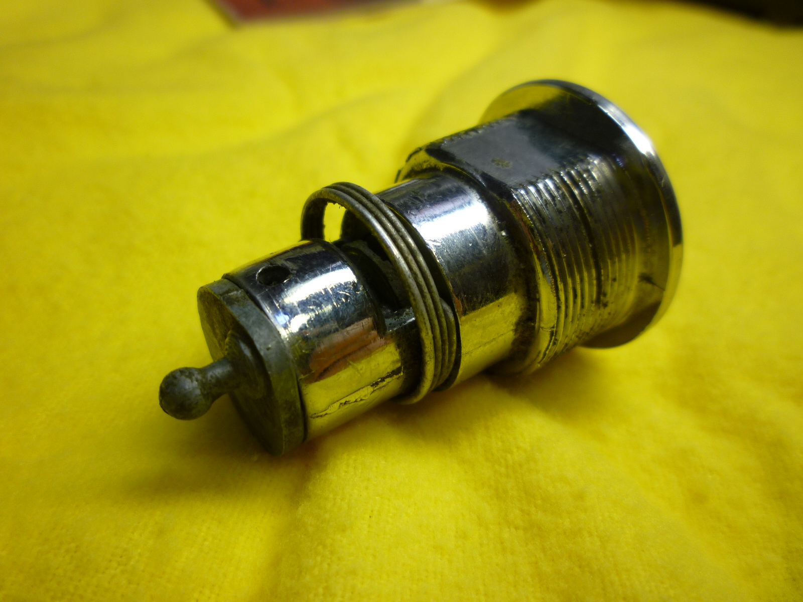
Al also didn't have any keys for either the glove box nor fuel release lever locks. So he sent those locks out too. The fuel release lock is old hat as I've done a couple before. However, I'll detail doing the glove box lock since it is constructed differently than any others in the car.
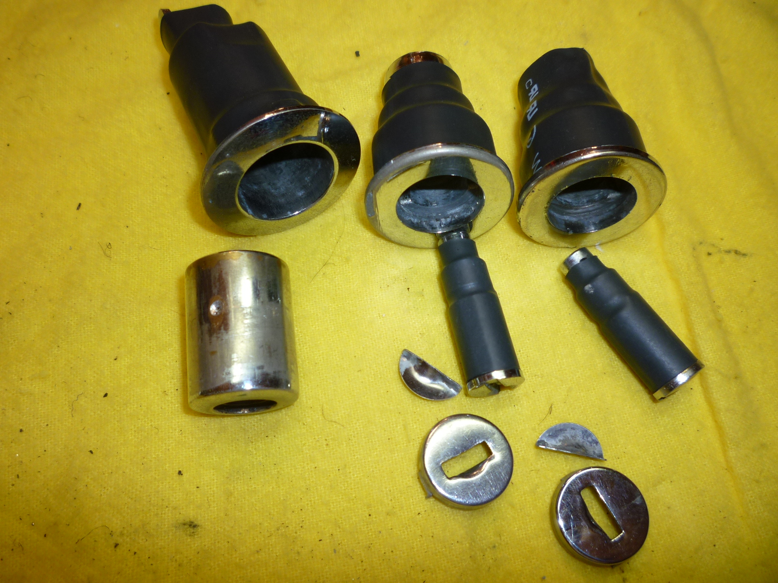
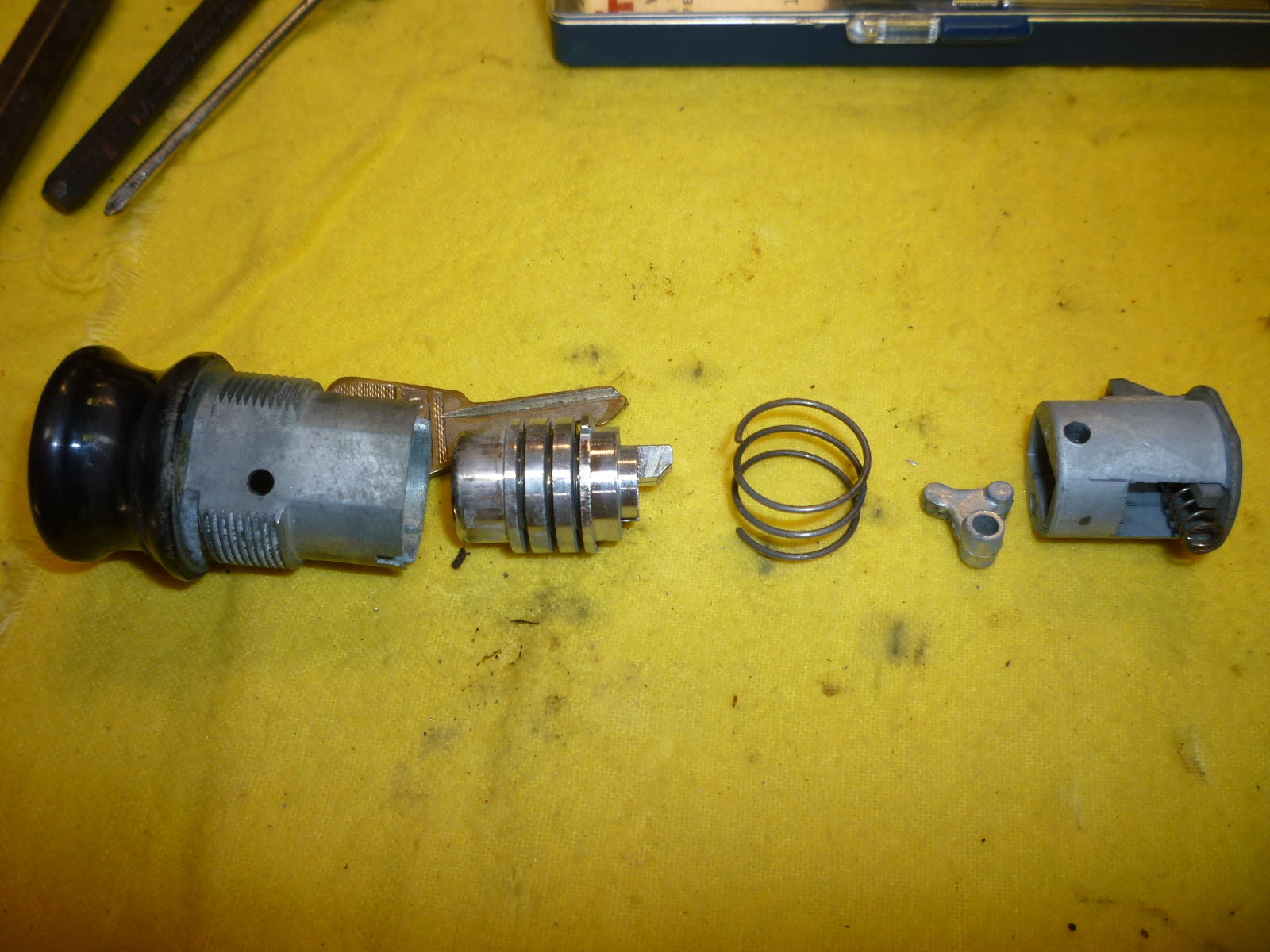
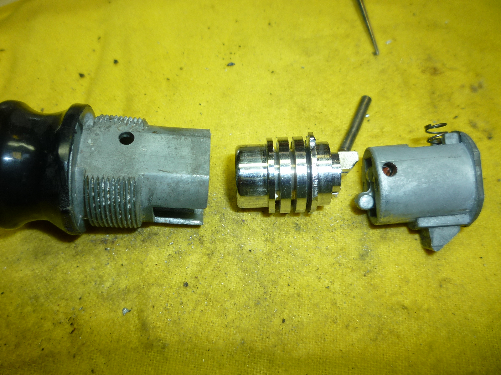
Taking it apart is pretty straight forward. There's a pin in side that holds everything together. Once that is driven out, the plug and cylinder are free, along with several other parts. From left to right, there is the lock housing, cylinder w/plug, return spring, actuating lever and tail piece with latch and spring. As the push button (lock plug and cylinder) is pushed in, the actuating lever is rotated and this retracts the catch you see in the left picture. The spring returns the push button when it is released. The catch spring keeps the glove box door latched except when the button is pushed. When the lock is locked, the plug is turned 1/4 turn so it hits against a stop preventing the push button from being depressed.
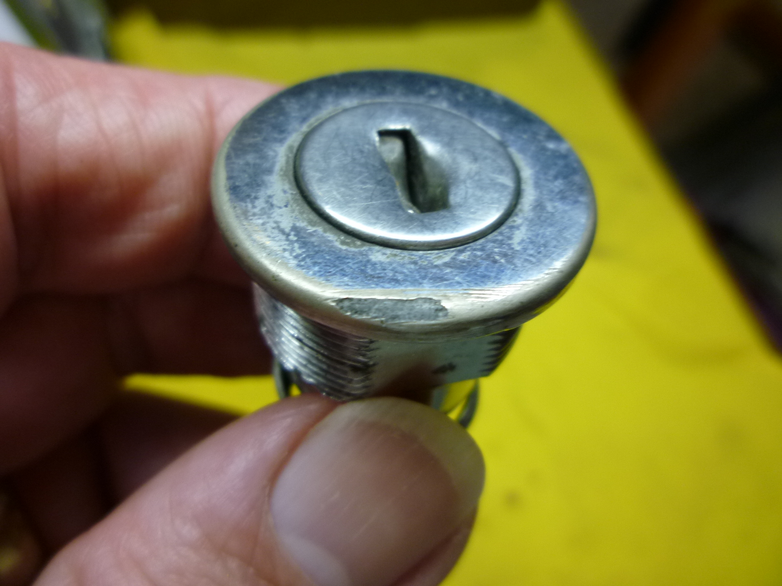
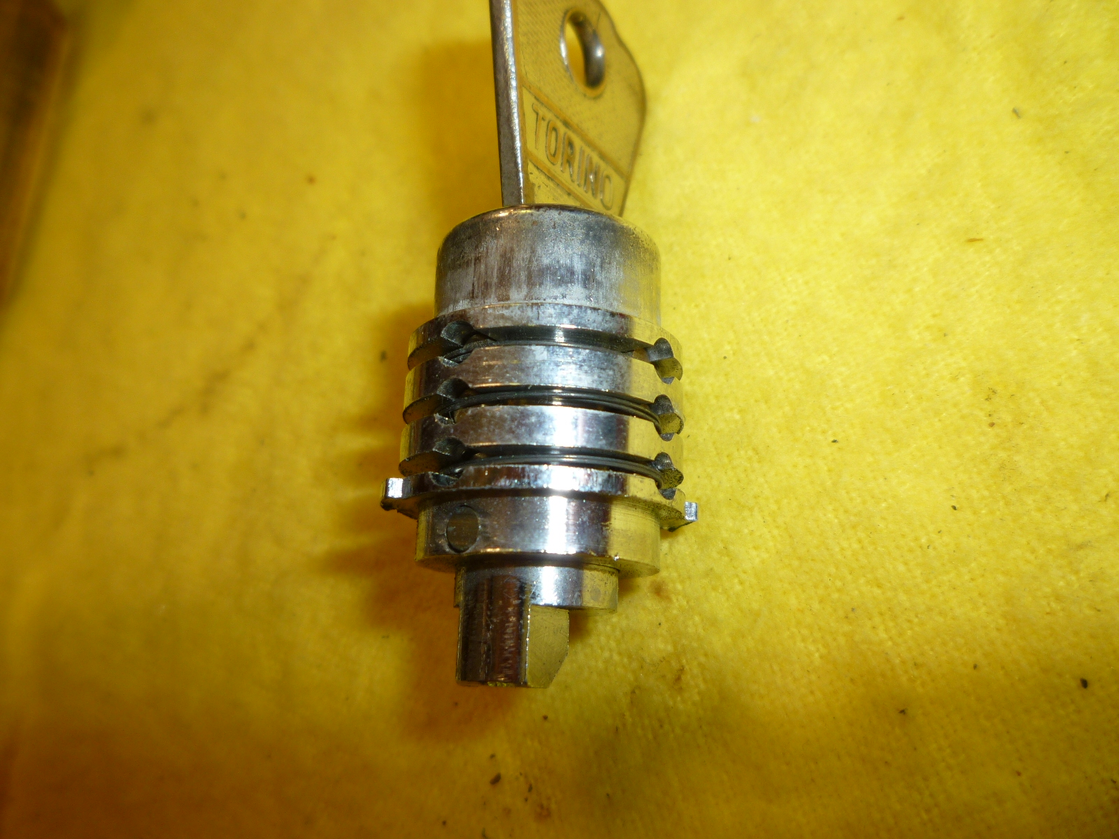
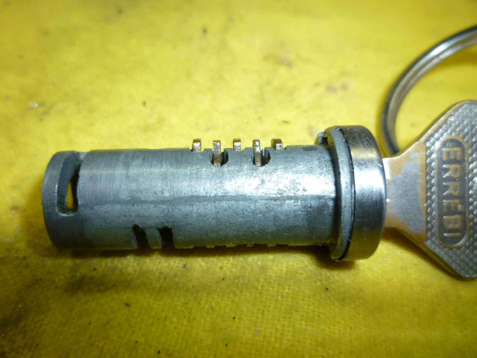
The unusual thing about this lock is the method that is used for the upper pin springs. If you click on the picture to see it enlarged, you can see that there are circular springs going around the over each pin location. There are only three pins in this lock with two sets of upper pins, 1/4 turn apart. So in one position (with the key out) one set of upper springs keeps the lock locked and in the other position, the other set of uppers are used. So the key can be removed in either position, either with the glove box locked (button will not depress) or unlocked (button can be depressed). There is also a fixed pin that isn't shown that fits into a slot that only allows the 1/4 turn.
The same key blank that fits the trunk fits into the glove box and can be keyed the same. So I'll be changing pins so Al's existing trunk key will now work the glove box lock.
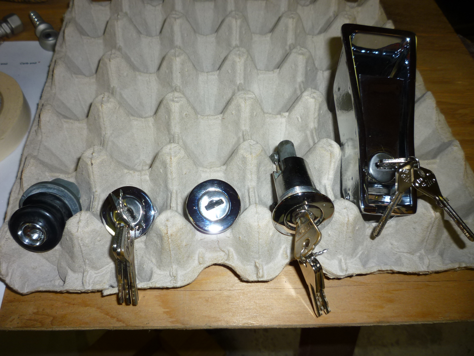
I picked up the various lock parts from the chrome plater the other day. They did a nice job and the heat shrink tape kept everything fitting properly, with just a couple of minor adjustments needed where the plater needed to remove the tape to wire the up the item for the plating process.
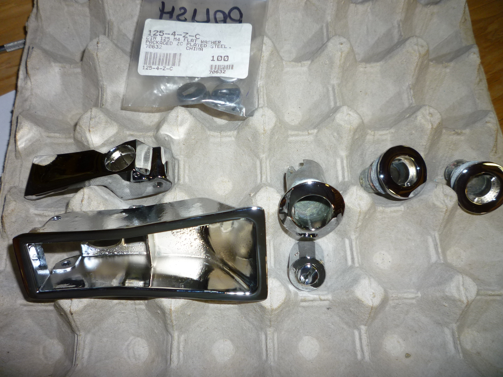
Among the parts I sent out were the bezels and door flaps for the fuel lever and door locks. These are stainless steel, so just needed polishing. In particular the door flaps are quite small and I was afraid that I would lose one if I tried to polish them myself. As you can see, the professionals do an excellent job.
Re-assembly of the various locks was pretty straight forward except for the glove box lock. When I took it apart, the innards just popped out without me being to discern exactly how they were assembled originally. The major issue was that there was a buried lever fitted onto the pin that holds everything together. At first I couldn't think of how to keep it in place while fitting the halves together and then getting the pin installed through everything. Eventually, I figured out a solution. I cut a short piece of #10 copper wire and used that to hold the lever in place within the inner assembly. Then, once both halves were put together, the pin pushed the wire out the far side as it was installed.
The last issue was the key that Art supplied for the door locks. It was well worn, so the lock was catchy, not wanting to turn except after some jiggling. The problem was the key no longer was lifting the wafers high enough to let the cylinder turn easily. I tried adjusting the key machine to not cut as deep of cuts, but I could only cut .005" less and that wasn't enough. So I decided to take apart one of the locks and cut new keys by measuring the depths needed. You can see how the wafers stick up with the worn key on the left and that they are flush with the cylinder using the new key on the right.
Once that was done, I cut extra keys so Al would have spare sets. Here's everything ready to be shipped back.