Front Suspension
Recently I've been helping Lowell Brown sort out the front suspension on his 330 GT (SN 8855).
He took it in for an alignment and was told that the upper outer A-arm bushings were worn. After looking in an old FAF parts manual, sure enough, these are on the 'high' wear item list. Assuming the best, Lowell ordered up a set of new bushings.
We jacked up the front and put the car on jack stands. Then we took the pressure off the suspension by using scissors jacks to raise up under the king pins (after removing the grease fittings there). There was quite a bit of slop between the pivot pins and the bushings. Probably 1/10 inch or so in play when pushing and pulling at the top of the brake rotor. So it was disassembly time.
First came removal of the brake caliper assembly. This came off in one piece without having to remove the pads or brake line. One victory. Then it was time to remove the cotter pins holding the nuts on the ends of the pivot pin. Simple you say, but it wasn't. I think that US sized cotter pins were used that were too large for the hole, but were tapped into place with a hammer. Of course, removal of a cotter pin is never as easy as insertion. You can't straighten the pin like new. It took over an hour to remove the first cotter pin and that got done only because there's a hole in the end of the suspension pin that allowed us to drill the cotter pin in two pieces. Then each half came free. The other cotter pin was easier since I started by drilling it in two.
The nuts on the ends of the pivot pins weren't on very tight. In addition, one A-arm came off the taper on the pivot pin quite easily. We didn't realize it then, but that was a harbinger of problems to come. In any case, the pivot pin was out and we removed the old bushings.
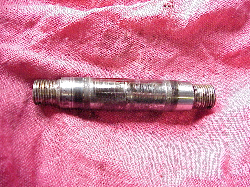
| As you can see, the pivot pin also had quite a bit of wear. So we simply disassembled the other side as we couldn't go any further without having replacement pins. |
|
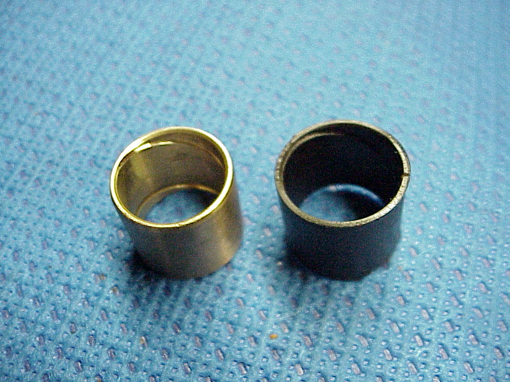
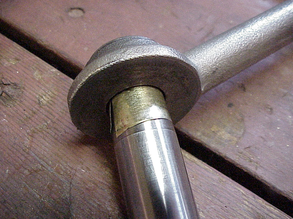
| The new bushings were bronze while the old ones were a plastic of some sort. Notice the grooves on the inside of the bushings. These are to allow grease to move from the injection area in the center of the pin out toward the ends of the pin. When the bushings get worn enough that the grooves are mostly gone, the grease doesn't go where it needs to be. |
|
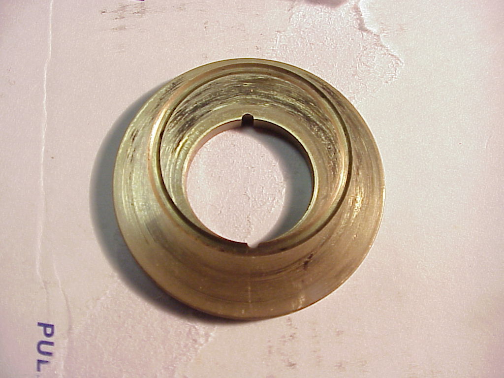
| At the each end of the housing, there is a large brass washer that become the bearing surface between the A-arms and the housing. These are also interesting with respect to greasing. You can see the washer on the right. Notice the off center machined circular groove that just touches the center hole on one side and runs to the outside of the washer. You will also see a small slots in the center hole at the top and bottom. The far side of the washer also has a circular groove, but it's touches the center hole at the slot at the top. This washer butts up against the end of the bushing. So grease starts in the center of the housing, runs through the bushing grooves, into the washer groove on the near side, through the slot and into the washer groove on the far side. Enough of Ferrari engineering, but I was pretty impressed. |
|
The new pivot pins arrived. There were a couple of issues. First, the new bushings needed to be reamed to fit the pins. Lowell got that done at a machine shop. They did a beautiful job, taking off just .001" on each side for a total of .002". The pins fit in quite nicely. The second issue was that there were no cotter pin holes in the ends of the pins. To install the bushings, Lowell, after a lecture from Carlos Durante, a well-known Ferrari mechanic about not driving them in, used the new pivot pins themselves and a lot of washers to gradually push the bushings in place by stacking the washers and tightening the nuts on each end of the pivot pin. This was quite time consuming as washers had to be added when the nut would bottom on the pivot pin threads and also the washers often became hung up on the sides of the pivot pin tapers, requiring that the assembly be loosened and readjusted. Further, there were different sizes of washers needed (all hand ground down to fit) and the steering wheel would have to be turned side to side to get the clearance at the front nut and then at the rear one.
So, now it was simply time to reassemble everything, drill holes for the cotter pins in the right places and we would be done. Wrong again. When I was putting the A-arms onto the new pins, they would tighten up against the housing and brass washers before fitting tight onto the tapers. Ideally, the A-arms should seat onto the tapers with no end play but still have the whole assembly rotate easily against the housing. We did a lot a measuring with a digital caliper and comparing the old and new pins to determine what was going on.
Before we disassembled the A-arms, we marked the locations for the cotter pin holes. I first tried to mark them with a center punch, but that just dented the punch. Then I tried to use a small drill, but it only shined the threads where I was trying to drill. So we ended up just using a magic marker. Lowell took them into the machine shop and they tried a hardened bit which also dulled without doing anything. So they had to use an end cutter on a milling machine to cut through the hardened surface. From there, a drill was used, but there was also a hole in the ends (where I drilled through the old cotter pins) of the new pivot pins. That hole was also hardened so the drill dulled when it hit that. Back on the milling machine, the end cutter was just long enough to cut through the center section. The old pins weren't hardened where the threads are. I think someone screwed up and forgot to anneal the ends. (Since then I've found out that the new pins are to be assembled using Nylock nuts as shown in the 365 2+2 parts manual).
Ferrari provided several thickness of the brass washers that would allow adjustment of the end play and tightness. These run from 2.75mm (.108") to 3.15mm (.124"). Lowell's were .111, .120, .121 and .124 inches in thickness with the large and small ones on one side and the middle sized ones on the other. The dimension of the housings were 1.731" and the gap on the assembled A-arms and pins was 1.935". So that left only .204" for both washers or .102" each. This was nine thousands smaller that the thinnest stock washer so clearly something wasn't right. For the washers we had, we needed about .043" more clearance.
Since the housing probably didn't get larger since it was made, and since the washers were all in the normal range, we finally decided that the inner tapered surfaces of the A-arms were slightly worn, thus preventing them from seating down onto the pivot pins properly. There were several solutions discussed over many days and phone calls.
- Assemble it with the nuts just tight enough to take up any end play. This was how it was when we took it apart. That was rejected as it would continue to allow wearing on the A-arm tapers.
- Get new pins from a different source and see if they were any different. This was also rejected since the old and new pins were identical as far as we could tell except that the new pins were longer, but the extra length was in longer threads at the ends.
- Machine the inner side of the A-arms. This could cause a slight binding since the inner ends of the A-arms can't be moved in as they are bolted onto the inner pivot pins with the bolt running through a machined groove in those pins. So that was out.
- Machine the existing brass washers down to .102" each. Lowell ground down and lapped two steel washers down to .102" and tried an assembly on the car. It was clear that the thinner washers were binding the back of the A-arms just as we suspected would happen in solution #3.
- Another idea was to have the inner tapers of the A-arms plated with hard chrome or nickel to bring them back to specification. Doable, but quite expensive as an anode would have to be made to evenly plate the surface. The taper only needed about .001" added to provide the .043" clearance needed.
- The final method adopted was to use some brass shim stock to fit between the taper and pin. This is available in .001, .0015 and .002" thickness. Once the A-arm and pin are assembled properly, there's no wear possible, so using brass wasn't an issue. Brass is also soft enough to resolve any wear patterns that exist in the A-arm taper. This ended up being the expedient solution for both cost and not permanently changing anything. If it didn't work, another solution could be tried. I had originally, in jest, suggested using a gum wrapper and it turned out that was about what was needed.
So Lowell ordered the three thicknesses of brass shim stock from Small Parts. We were pretty sure that the .001 size was what was needed, but they are cheap so it was better to have a choice.
| We wrapped a piece of paper sprayed with tack spray on the inside of the A-arm and then cut through both layers where the ends overlapped. We also cut the paper where it stuck out the ends. Then, after careful removal, we had a pattern for the shim stock. You can see one of the ones we cut using an X-Acto knife. |
|
| We assembled each pin with the shims and A-arms off the car and then measured the distance between the arms. These varied from 1.989 at 35 ft. lbs of torque to 1.974 at 50 ft. lbs. So we were in the right ball park. |
|
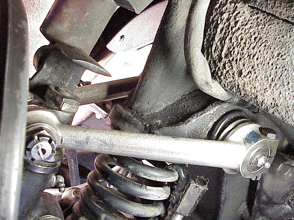
| The final torque was determined when assembling on the car. By mounting the A-arms so the inner ends were free and vertical between the shock and brake rotor, we could tighten them enough to remove any end play, but still make sure that they weren't binding. The right side (with the thicker set of brass washers) took 35 ft. lbs. while the left side fit with a torque of 55 ft. lbs. Then we took them apart and reassembled everything onto the inner pins. |
|
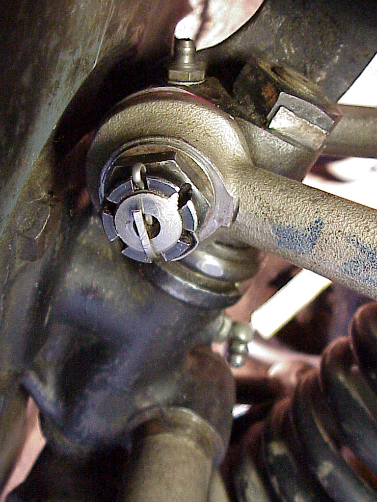
| After reading about cotter pins on Tom Yang's website, I ended up doing the ends the same way. Then a little dab of yellow paint, and we were done. |
|
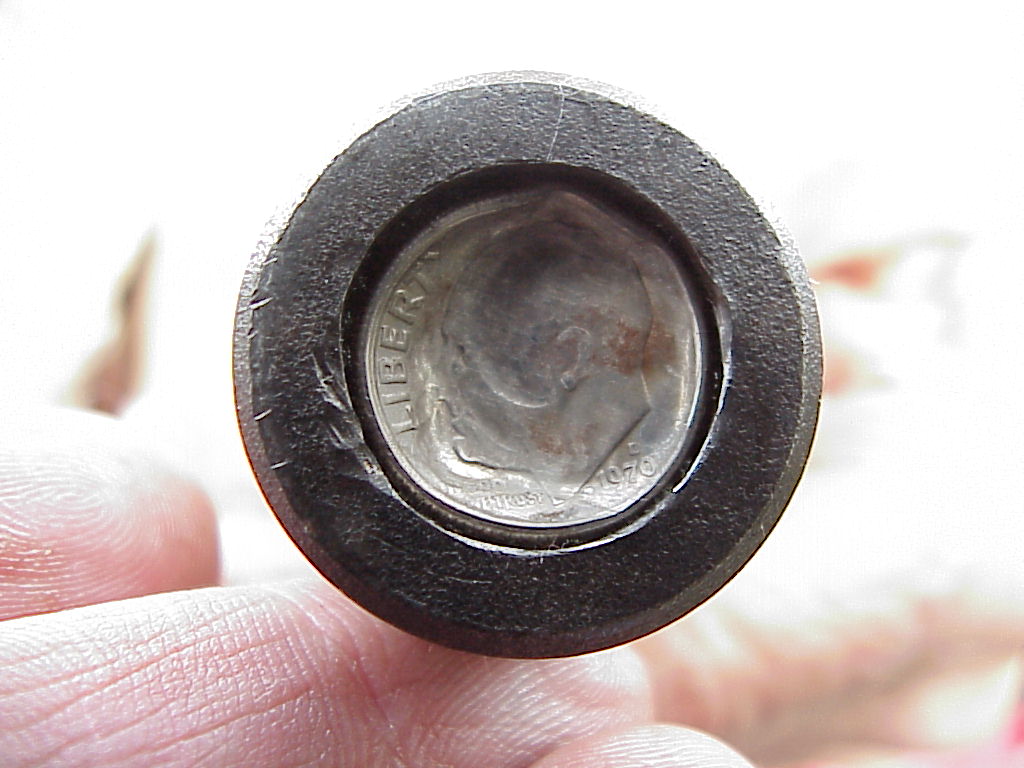
| Actually not quite. When Lowell was greasing the various parts we had apart, a cap from the end of the inner pin blew off. Earlier he had dinged it up some when taking out the pin for some assembly/binding tests off the car. After careful examination, the cap was actually a US dime, dated 1970 from the Denver mint. A little flattening and some filing on the outside put it firmly back in place so the greasing could continue. The other side has a nice brass cap, but at some point in the life of the car the one on this side must have been lost and a mechanic found that the dime would work. |
|
Then it was time for a test drive after the car was taken down from two jack stands, scissors jacks under each of the two king pins, and a hydraulic jack under the front frame crossing, a state the car had been in for the last six weeks, including the 6.7 Seattle earthquake. Lowell let me drive and it was a pleasure. First, his car has power steering whereas mine doesn't. Second, his steering is now nice and tight with no discernible play while mine needs the worm in the steering box machined to take the play out of the center where it wears the most. Anybody know someone that can do that? I can't tighten the worm peg to take the play out because as soon as you turn the wheel, you get into a lesser worn area and it's too tight.
The moral to this story is to keep your suspension well greased. Then the bushings don't wear out and you never have this problem. I'm almost afraid to jack up under the suspension on my car to see if I have any play in the upper pins. I have so many tasks yet to be done that I don't need another one.
Well I did jack up my car and it does need new pins and bushings too. Click here for the work on my car.