Front Suspension
After helping Lowell Brown work on his front suspension, I tested mine and found some looseness. I wasn't surprised given the mileage on my car.
There was play in both the upper and lower outer pins. A friend of mine in Australia had gotten pins and bushings made up and I got a set from him a while ago. They've been sitting on the shelf along with a bunch of other parts for projects on the car. So today I decided to start this project.
I had learned several things from working on Lowell's car. I started by just disassembling the upper pins as doing the lower requires removal of the spring.
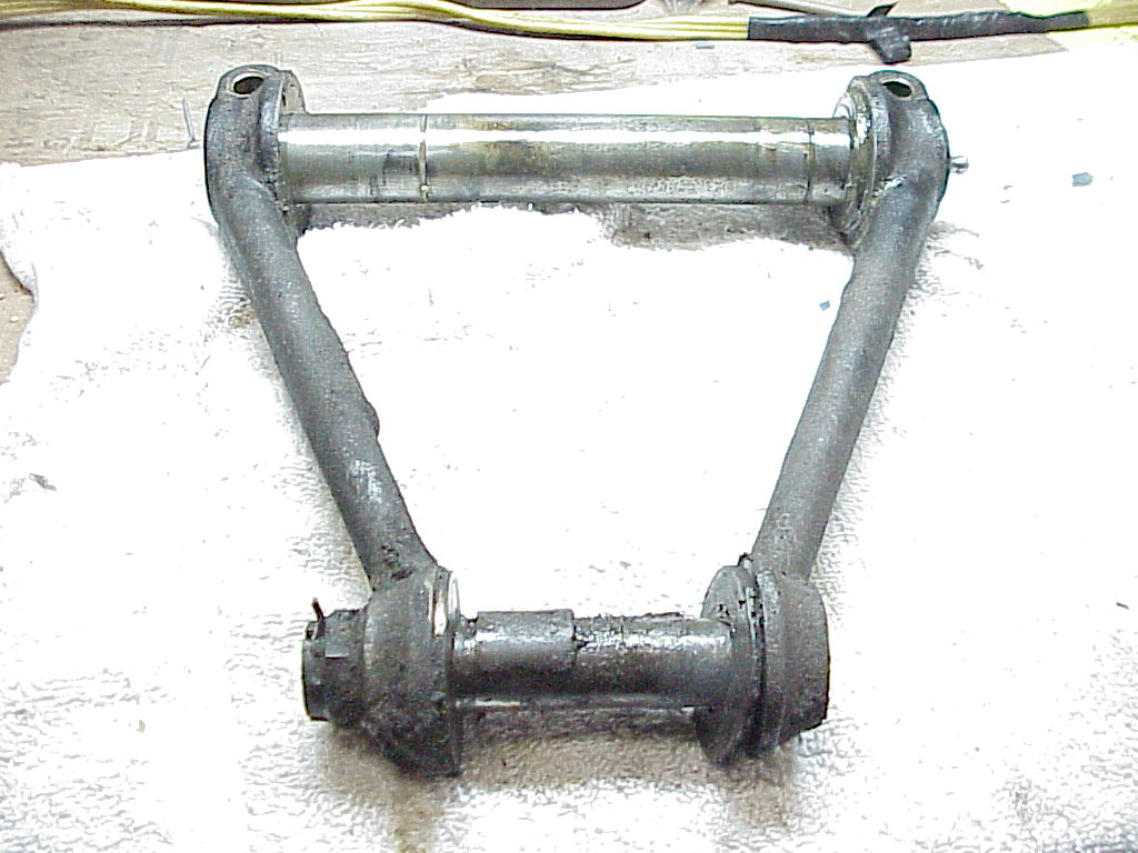
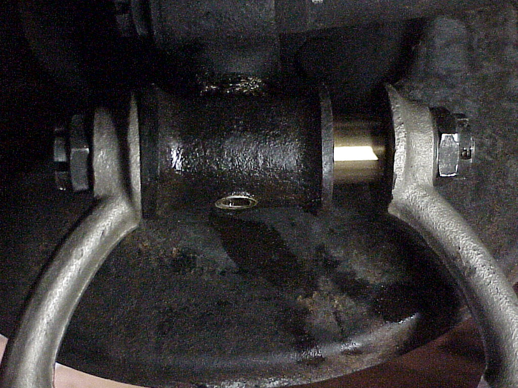
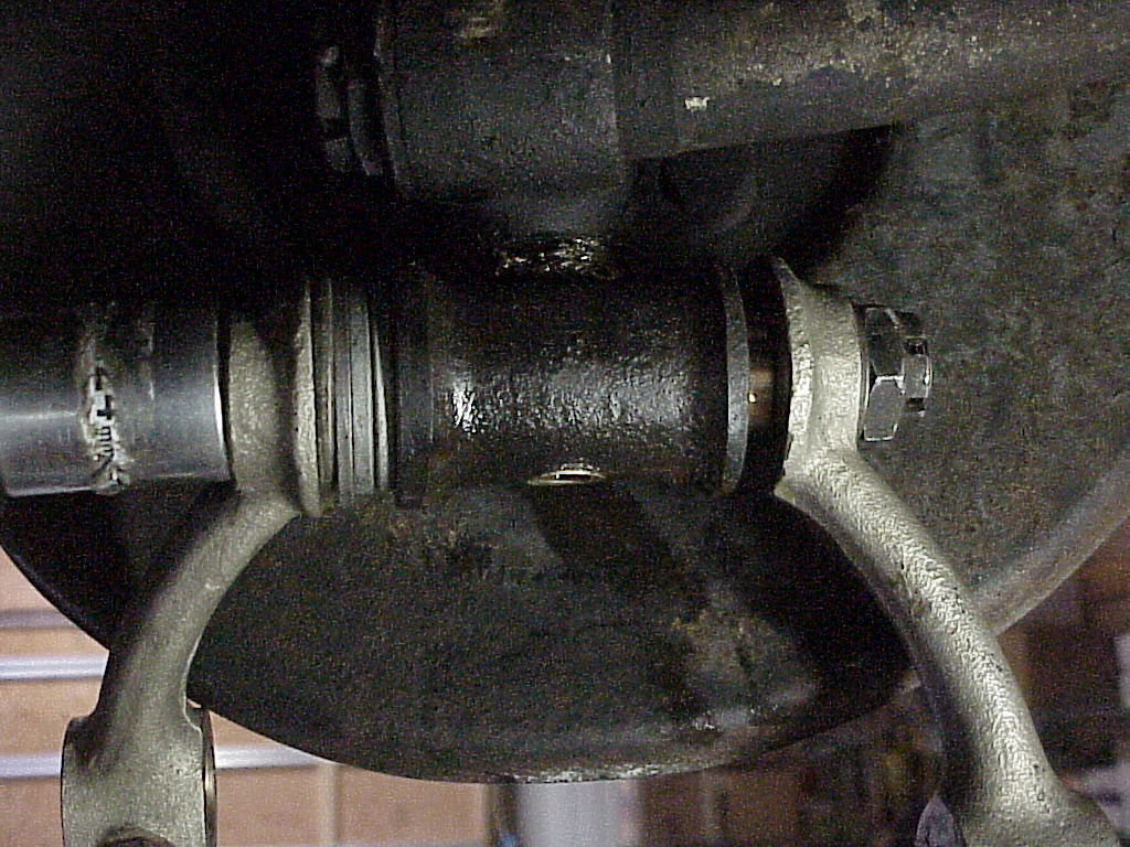
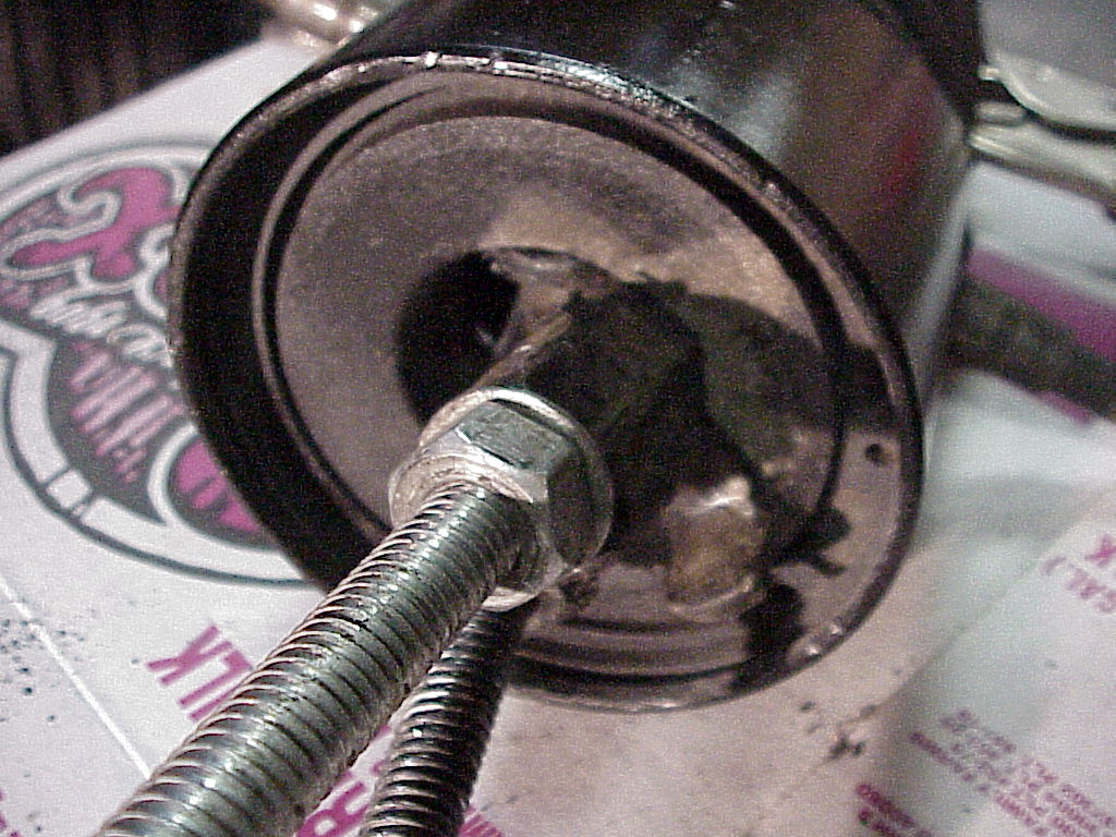
I couldn't get the cotter pin off on one side, but if you remove the other three ends, then the arm and pin will come off as a unit. You can see the cotter pin in the nut at the lower left. Once I had everything in a vise where it's easy to see and work on, the cotter pin was removed in a couple of minutes.
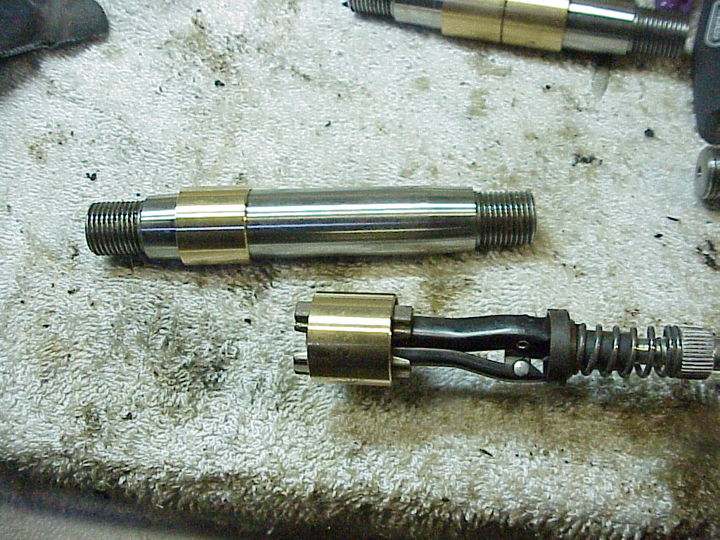
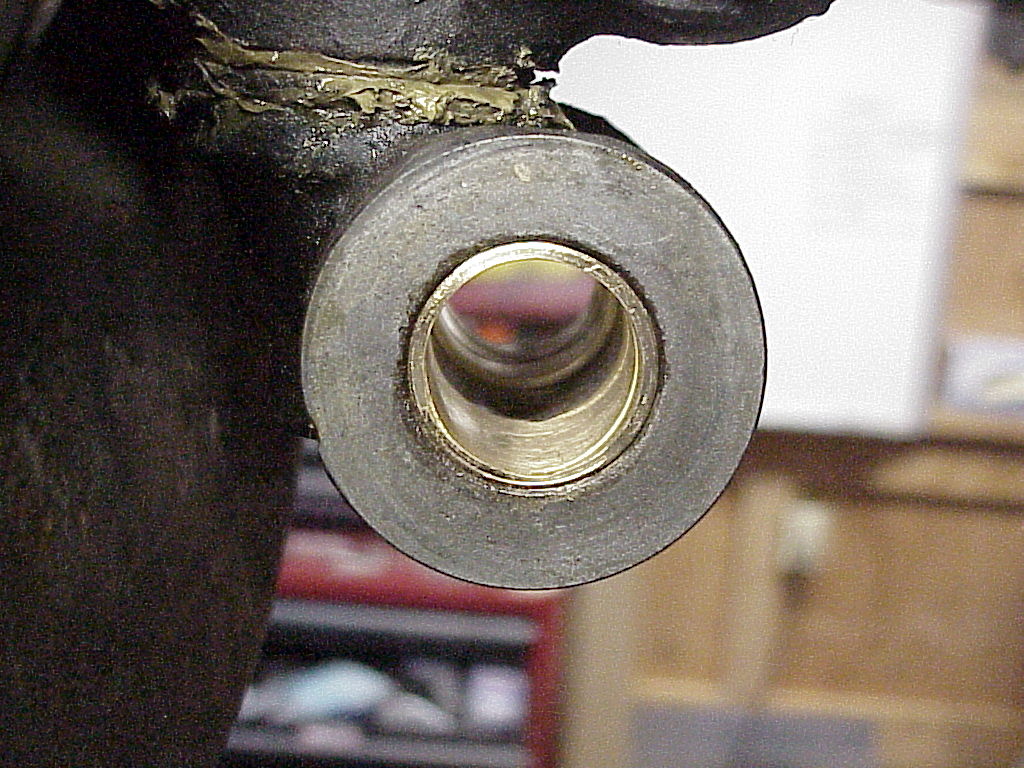
One of the things that needed to be done on some of the bushings was to hone them to fit snugly on the pins. Here you can see one bushing on a pin and the other ready to be honed.
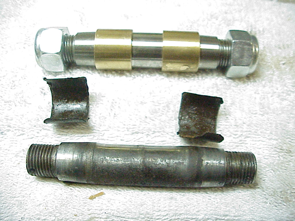
Here you can see the old pin (note the wear), old bushings (1/2 of each was worn out and gone) along with the replacement pin and bushings. You will notice that the new pin has Nylock nuts rather than castle nuts that use cotter pins for security. Ferrari switched to this method with the 365 2+2 suspension. The Nylock nuts give more accuracy when adjusting the end play as you aren't limited to moving the nut 1/6 of a turn at a time. And you don't have to screw around with the cotter pins either.
Putting the new bushings on the car isn't trivial. The bushings are brass, so you don't just drive them into place or they will get damaged. I ended up fitting one bushing onto a new pin and putting an arm and nut on that end. Then you put the pin through the suspension piece and put the other arm and nut on the other end. When you tighten that nut, everything gets tight and the bushing gets pulled into place. The nut will eventually bottom out, so you have to take it and the arm off and put several large washers on the inside of the arm. Then tightening the nut again will complete the process. This is pretty foolproof since the pin will prevent any deformation of the bushing and the parallel ends of the two arms will keep everything aligned properly.
 |
 |
| Starting with no washers | Washers on the left side and the bushing partially installed |
However, everything doesn't always work out like one would like it to. These bushings are a little too large in the outside diameter, so the inside narrowed down when the bushing was installed. So I will have to go back and do more honing on the one I have already installed. I'll take the others and remove some of the outside before installing any more. But it was time for dinner, so that's something to do tomorrow.
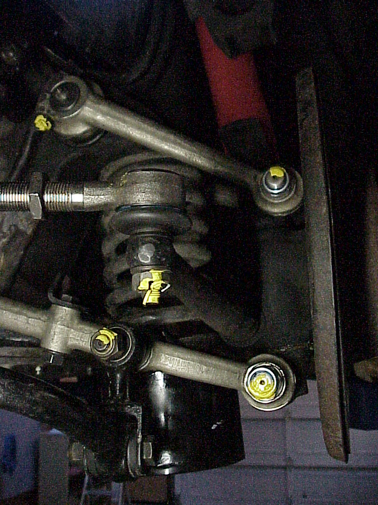
Here are a pair of new bushings all installed
A few days later, I got back to reaming out the bushings so the pin just fit in nicely. Then I assembled the two arms on the outer pin with the arms straight up. This allowed me to tighten the nuts, carefully measuring the torque while checking to see when I had just taken out the end play. Once I knew the proper torque (52 ft-lbs), I re-assembled the arms properly. This completed the upper arm on the one side.
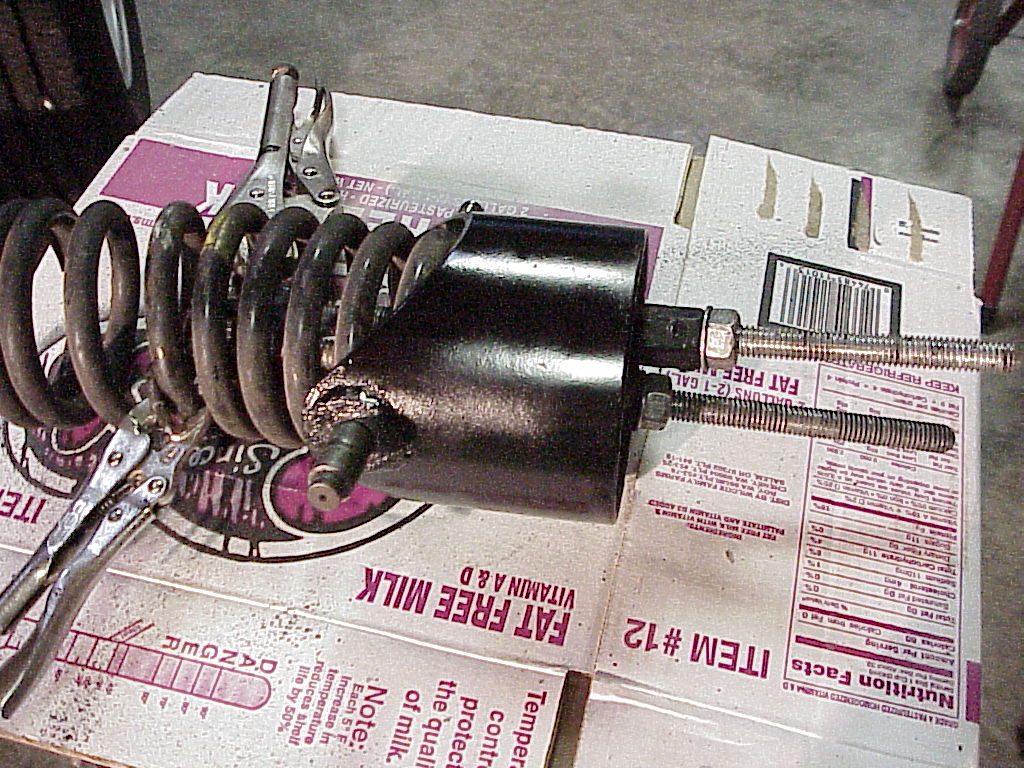
The next item was to do the lower bushings. This requires removal of the front springs. I bought a couple of internal compressors and then modified one so it would fit in the hole in the bottom of the spring cup. What I forgot was that I then needed to swing the arm that had to be down to fit through the hole, up into position to hook on a coil. There wasn't enough room inside the spring to do that. So I ended up using my very old simple compressors I bought in '75 to do the struts on my 240Z.
 |
 |
As you can see from the pictures, I turned the bottom hooks over and just let them rest against the plate inside of the cup at the bottom. I had to spread the coils at the top to slip the upper hooks onto them. Then it was just a matter of lowering the lift with the suspension against a piece of wood to compress the spring. I just hand tightened the nuts and then raised the lift, leaving the spring loose and ready to come out when the lower arms were removed.
Once the spring was loose, the removal of the front A-arm was pretty straight forward. The stupid cotter pins were a problem again. I finally realized that I had new pins and new nuts, so I didn't care what happened to the old ones. So I just got out the air impact wrench, stuck the 24mm socket on it and just sheared the pins off. I just had to clip the ends of the cotter pins so the socket would fit onto the nut. It worked perfectly, only took a few seconds and I could have reused the pins and nuts again as they weren't damaged.
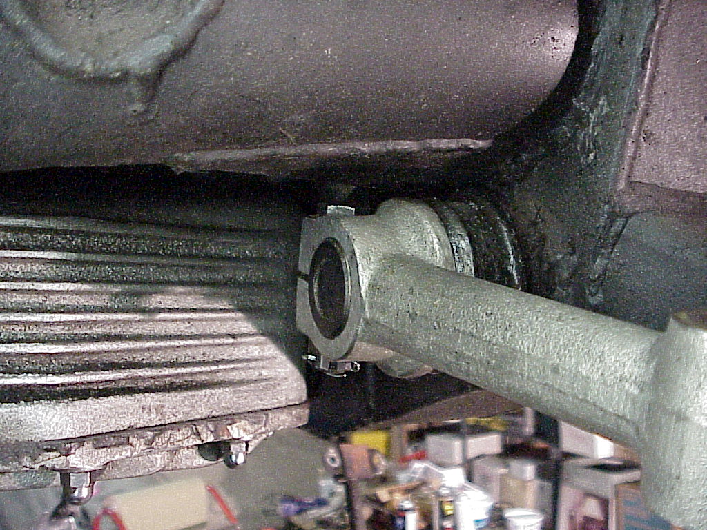
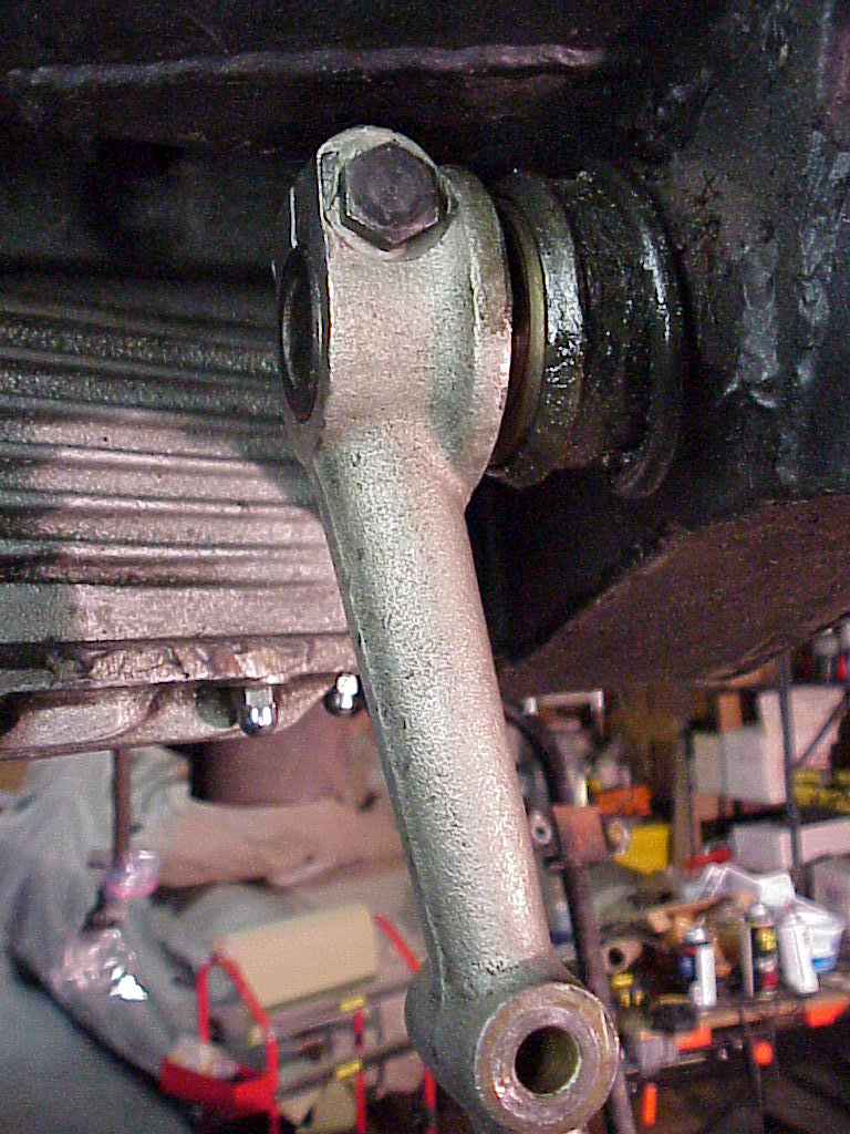
However removal of the rear A-arm required some maneuvering. You can't remove the bolt that locks the arm onto the inner pin because it hits against the frame. You can't slide the arm and pin to the rear as you hit the frame again. So you have to take the arm off the outer pin and spring cup, slide it to the rear a little and then let it drop down so the bolt is horizontal. Then you can remove the bolt and get the arm off the inner pin. You can see the arm, bolt and frame on the left and on the right, the location after dropping the arm down.
 |
 |
More to come
The upper A-arm on the left side had some play at the inner pin. This is unusual as these bushings normally aren't a high wear item. After looking at it closely, I found that the right end was missing its bushing, hence the play. After removing the pin which required driving it out with an appropriate sized socket and extension, I found the bushing had been pushed into the center of the housing. Using an arm off a small bearing puller arm along with a small vise grip pliers to hold it and a screwdriver to provide force, I was able to pull the bushing back into place. It had been out of place for quite a while as there was noticeably more wear on the left end of the pin where the other bushing was. I think that whoever put in that bushing ended up pushing it into the center or someone drove it into the center when removing the pin by using too large of socket. Anyway, after cleaning up the pin, it went back in place and everything works smoothly and there's no play now.
One thing I found out on the right side was that the Nylock nuts are thicker than the original castle nuts. This causes the nut to hit the brake dust shield when the steering is at full lock. Lowell suggested that I cut or grind off part of the face of the nut to make it thinner. I did one using a Sawzall, but it took about 10 minutes and two blades. So I went back to my neighbor Mike's place. He had an abrasive fiber cut-off wheel for an angle grinder. That only took about a minute per nut. Then I squared the cut ends off on the disk sander.
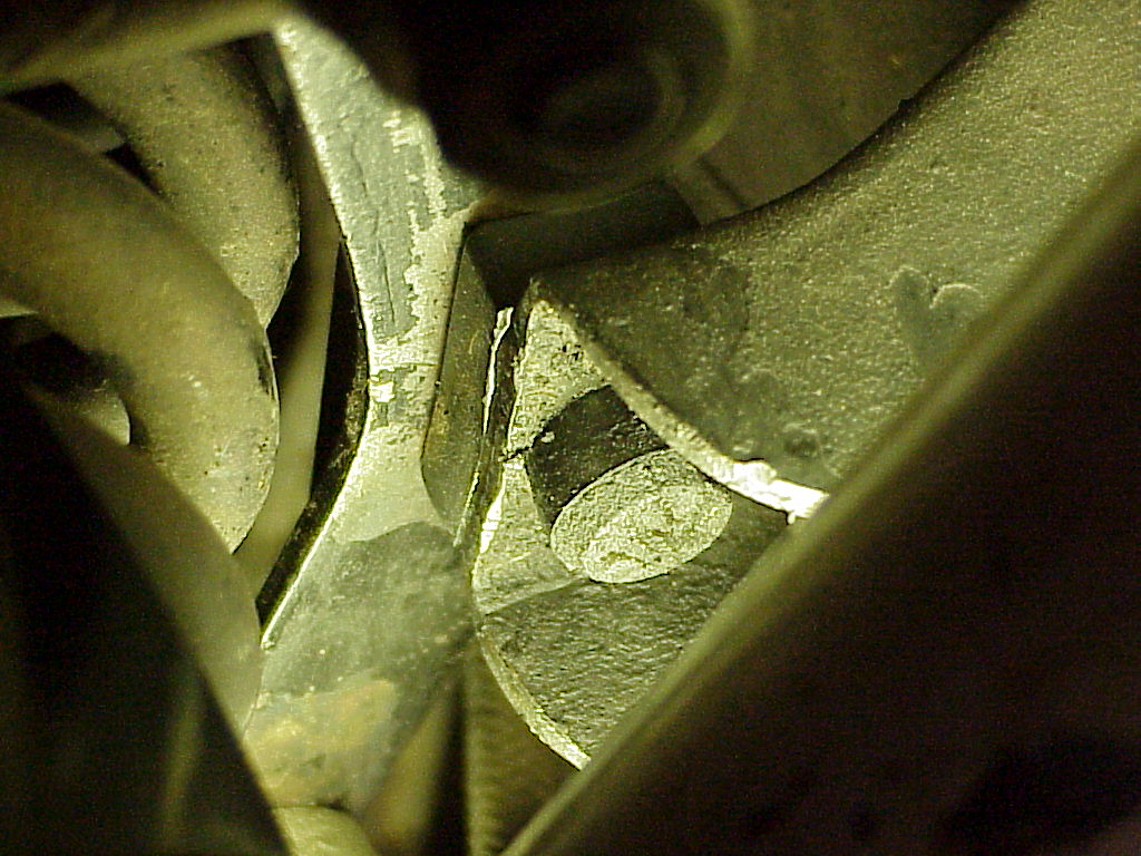
When I got ready to re-assemble the lower A-arm on the left side, I couldn't get the end play removed by tightening the nuts. Each arm has a tapered hole that mates with the tapered portion of the pin. I tightened both nuts up to 100 ft lbs and decided that more tightening wouldn't remove the end play (still .022" at that point). So I disassembled the arms from the pin and carefully looked at everything. On one end, I could see some extra metal embedded in the arm. You can see it where the arrow points.
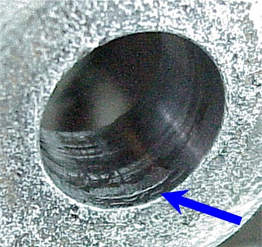
I couldn't remove the metal by prying it out, so I ended up using a small drum sander on a Dremel tool. That smoothed everything down nicely. Then it only took 72 ft lbs to remove all of the end play while still letting the arms swing easily.
| A-arm location | Torque |
| Right Upper | 52 ft lbs |
| Right Lower | 52 ft lbs |
| Left Upper | 65 ft lbs |
| Left Lower | 72 ft lbs |
Final Torque Values
When I was cleaning the spring and cup from the left side, one of the spring compressors bent and both hooks came off the spring. I was lucky in that there wasn't any part of me in the way when the spring flew off. It simply hit the wall a couple of feet from where I was working.
It did make painting the cup easier since the spring and compressors weren't in the way.
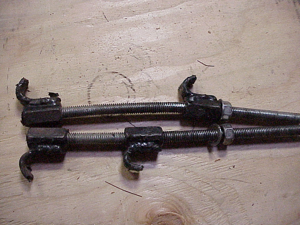
Here's another simple spring compressor made by Dave Wolin that works on cups with a hole in the bottom like the 330 GT.
It is made from a couple pieces of 1/4" bar stock and either a length of all-threaded rod or a long bolt that is completely threaded. A nut or two does the tightening.
|
|
|

Now that everything is back together, I need to re-center the steering wheel again and take it to a frame and alignment shop to get proper toe-in on the wheels set.
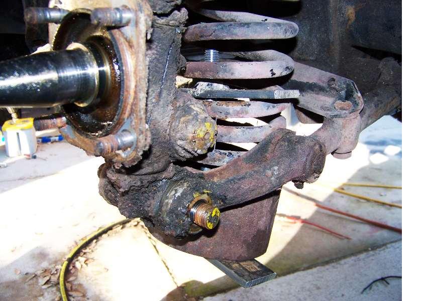
Just when I thought I was done working on the suspension, I discovered an error when I was greasing everything. It's hard to see in the pictures above, but the grease fittings for the shafts that hold the spring cups are supposed to be facing down. I got it correct on the right side, but the left side has them on the up side of the lower A-arms. It makes it hard to grease since there are other parts in the way of the grease gun. It wouldn't be so bad if the parts involved the upper A-arms, but to remove the lower A-arms, one has to compress and remove the spring assembly.
Two and a half hours later, the A-arms are now in the right position and everything is greased. So the suspension is finally done.
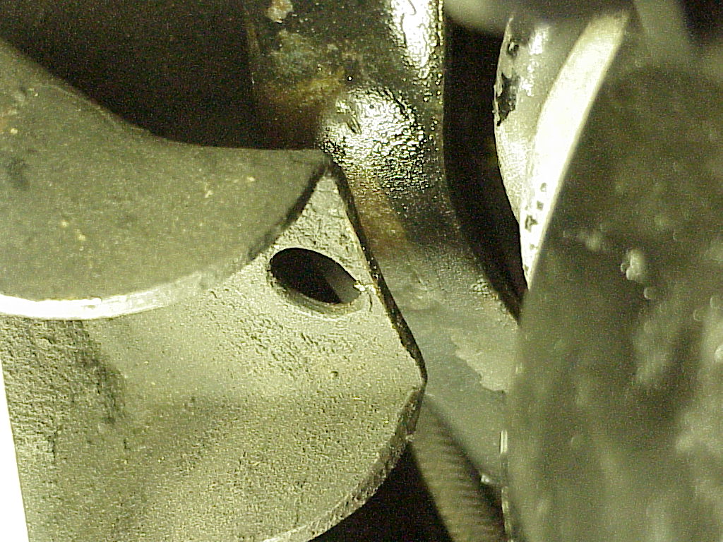
The last parts for the front suspension arrived today courtesy of Mike Marzon, past owner of 9229. There are supposed to be rubber bumpers that limit the travel at the bottom of the suspension. These are difficult to find, but Mike located them at UK Ferrari. I asked him to get some extras for both Lowell's and my cars. On the left you can see the hole where the bumpers are supposed to go.
 |
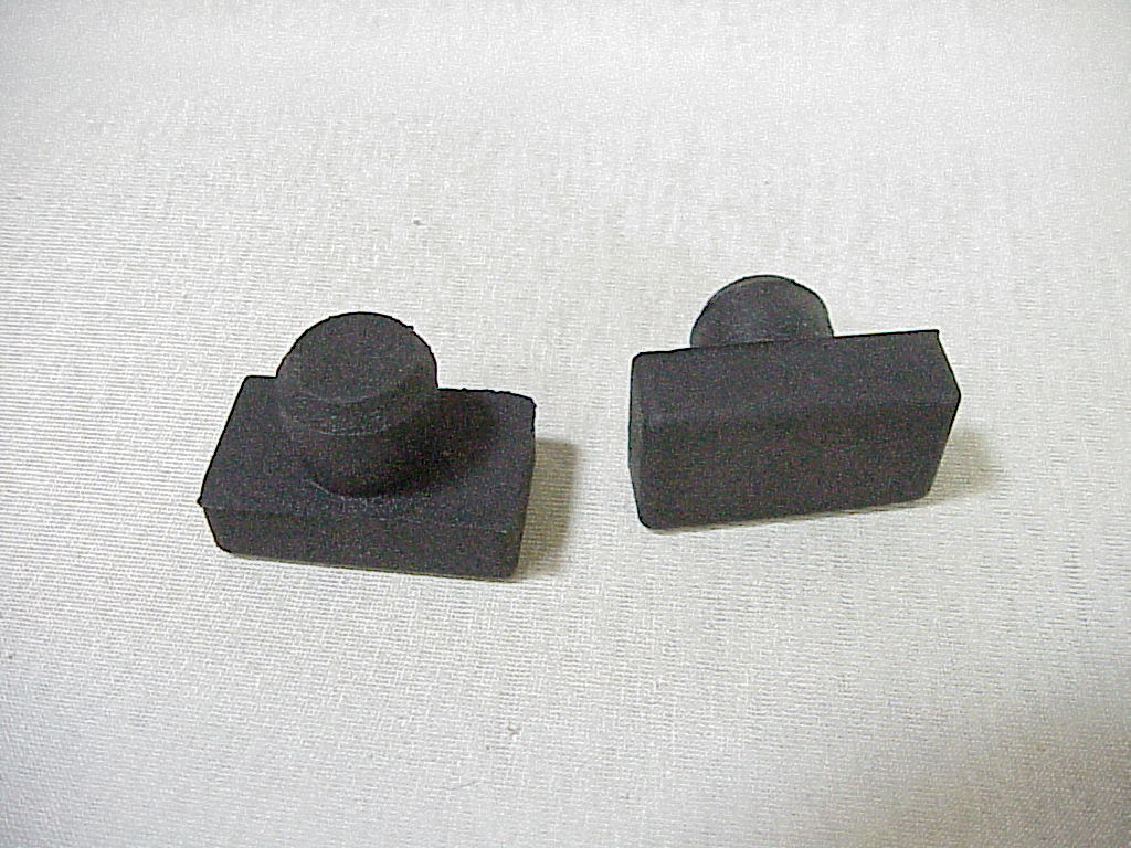 |
Installation isn't too easy. When you have the car jacked up on the frame, the suspension settles down where the bumper is to be installed. So you have to have that corner of the car supported on the suspension to allow working room. Then it's a matter of fitting and prying the rubber stopper through the hole little by little until it's all the way seated. Once the stopper is started in the hole, you can let the car settle on the suspension a little and that keeps downward pressure on the bumper so it can't pop out while you are working on it. Here is what it looks like when installed.