Inner Fender Panels
I've looked around for original inner fender panels to replace the 'signs' that were on the right side. A couple of leads, but nothing was the right size. In order to facilitate that search, I took a couple of pictures and then annotated the various dimensions right on the picture. Then I could email those and whoever thought they might have the right part would be able to know for sure.
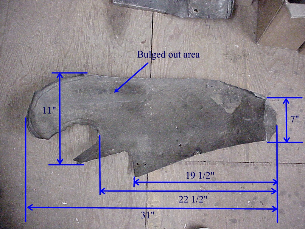
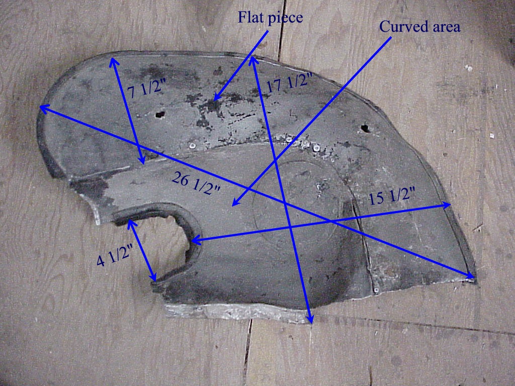
Since my search was for naught, I've decided to make them. But first, when I was looking at the originals from the left side, under all of the paint and undercoating, there was a long crack starting at the seam to the right of the curved piece (right picture above), running up and around to the left a little ways.
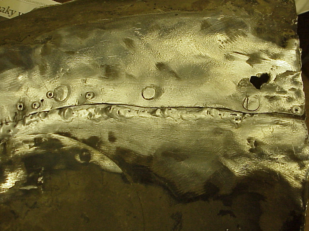
So I needed to fix this. As I'm in an evening welding class, I had lots of choices. First, I decided to see how my little 110 volt MIG would work with aluminum. The book says that it should. So a spool of .030 aluminum wire and connecting to an Argon tank in class and I was in business. Well, not quite. It seems that the voltage selection on my MIG doesn't really go low enough to work with aluminum properly. The wire would melt at the tip rather than at the work as it should. Then there was just a long arc filled with splattering aluminum. Neither the instructor nor another student who MIGs thin aluminum all day long at his job could get it to work. So the second choice was to use a TIG process. [A couple of years later] I finally figured out why my MIG wouldn't work. The aluminum wire spool didn't fit on the feed axle quite right, so it was binding. This would cause the wire to stop feeding and when that happened, it just burned back to the tip. This became obvious when I tried to use a new spool of steel wire from the same company, with identical results and realized that the plastic spool was the problem.
For those of you not familiar with welding, there are four basic methods. The first is the traditional gas flame (oxy-acetylene usually). The second is the arc welding using a fluxed stick rod for the electrode. The third is MIG (metal inert gas) where a electrified wire is fed through a nozzle surrounded by an inert gas (usually CO2-Argon or Argon, depending on the metal). The last is TIG (tungsten inert gas) where a tungsten electrode is electrified and surrounded by an inert gas. With a MIG, filler wire is continuously fed into the puddle. With a TIG, the electrode is simply supplying the heat to melt the base metal. Any extra filler metal is supplied by a separate rod just as in gas welding.
As I had not done much TIG work, much less on thin weathered aluminum, I spent a few hours practicing on material of the same thickness (.050"). After I finally got fairly competent (at least I could fill in the holes I burned in the material), I started on the splash shield. It took quite a while since the material was so thin. I would only do a small piece (1/2" or so long) and then move to another area to prevent too much heat buildup and warping in one area. Then I had to fill the holes where I let it get too hot and melted the base material back from the crack. But in the end I persisted. Not too pretty, but then one doesn't look under the fender everyday and a layer of protective undercoating will cover it right up.
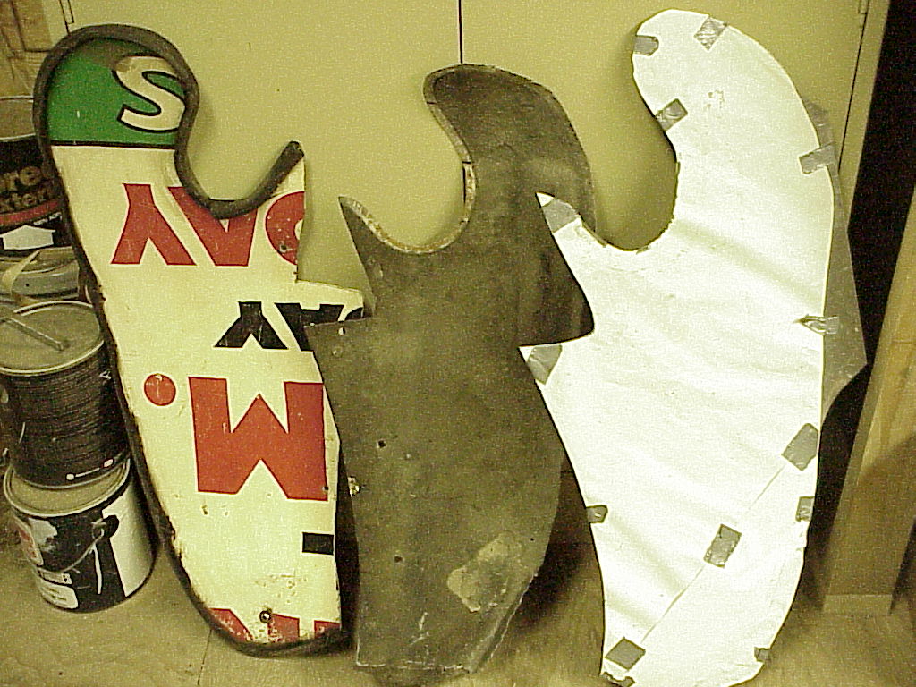
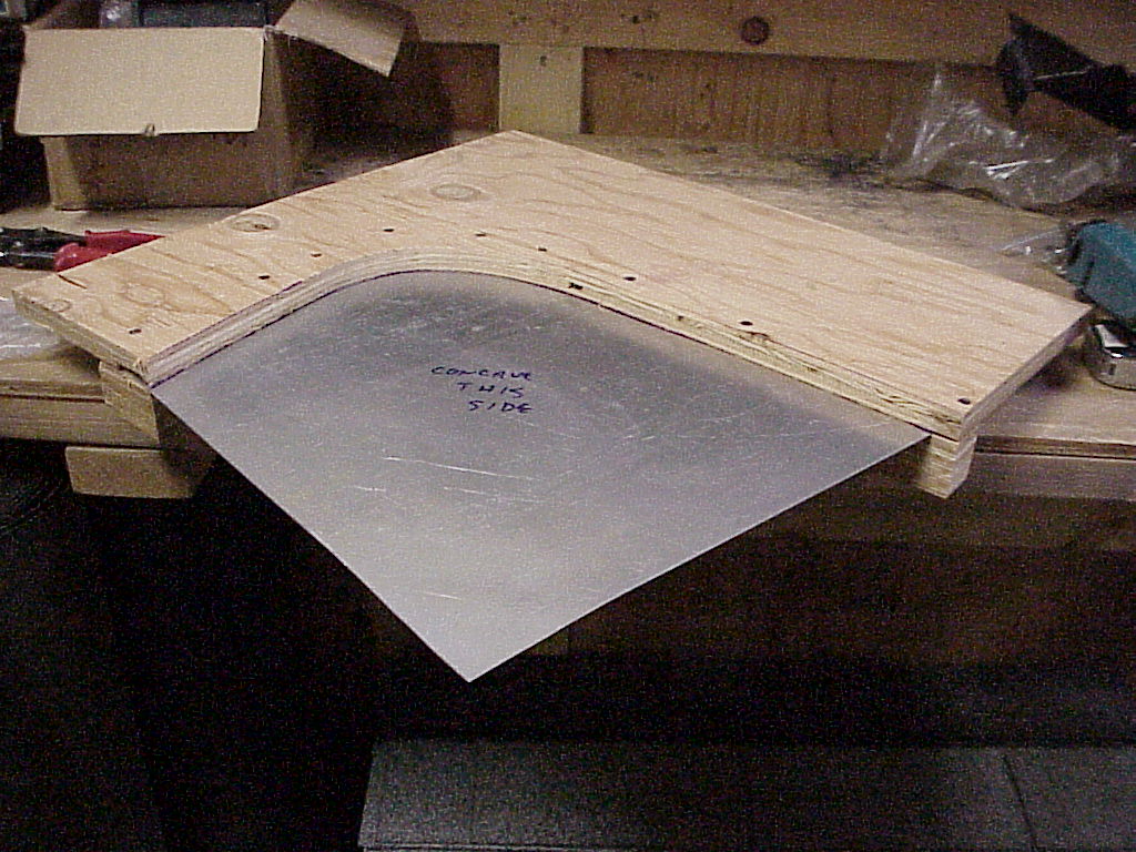
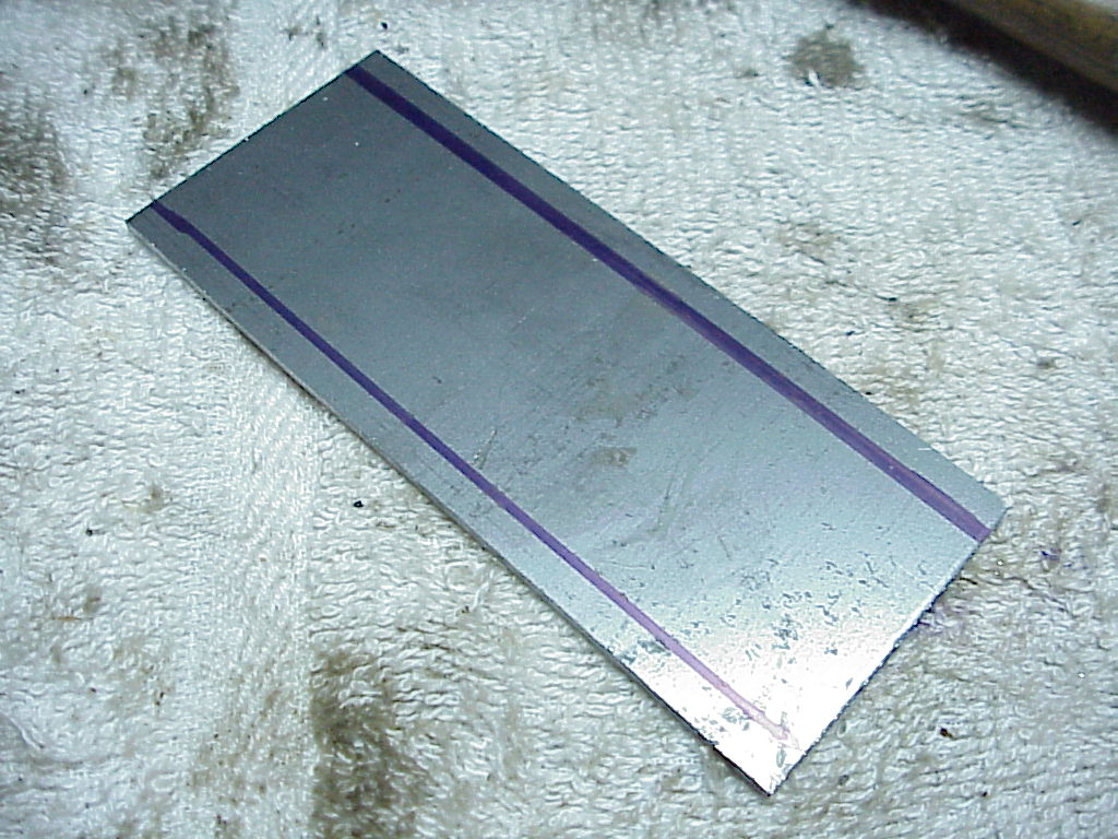
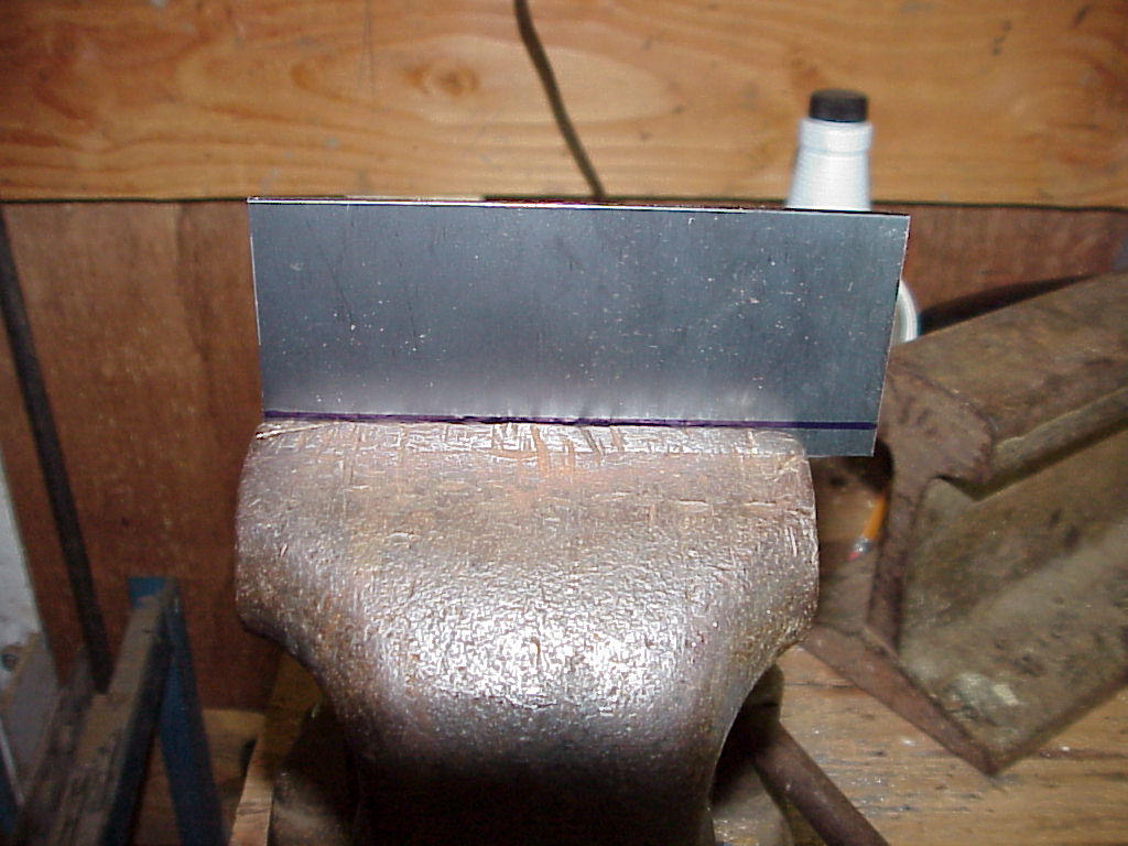
Now that that was out of the way, it was time to start making the replacement parts. You can see the 'sign' one on the left, the left side original in the center and the newly cut replacement one on the right. Since the left and right side are mirror images, I decided to use the original for the sizing and then just beat it into the opposite shape. I first tried tracing on the aluminum sheet, but due to the curve of the original, I wasn't sure that it would be right after working the metal. So I got a large sheet of paper, wrapped it over the original and traced onto it. Then I unwrapped it and taped it on the new piece and cut around the lines. For the long fairly straight cuts, I used snips. For the tight inner curves, I used a jig saw with a metal cutting blade.
Now my panel beating bag and hammers just arrived from Eastwood. So you'll have to wait for me to practice a while before I can finish the story.
It took a while, but I finally got back to working on these shields. My first try wasn't too successful.
 |
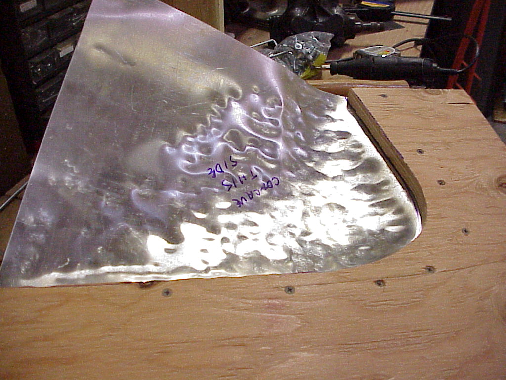 |
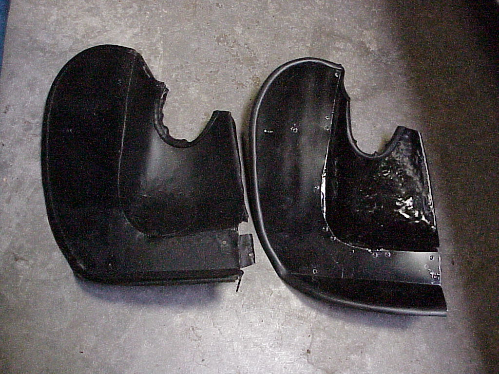
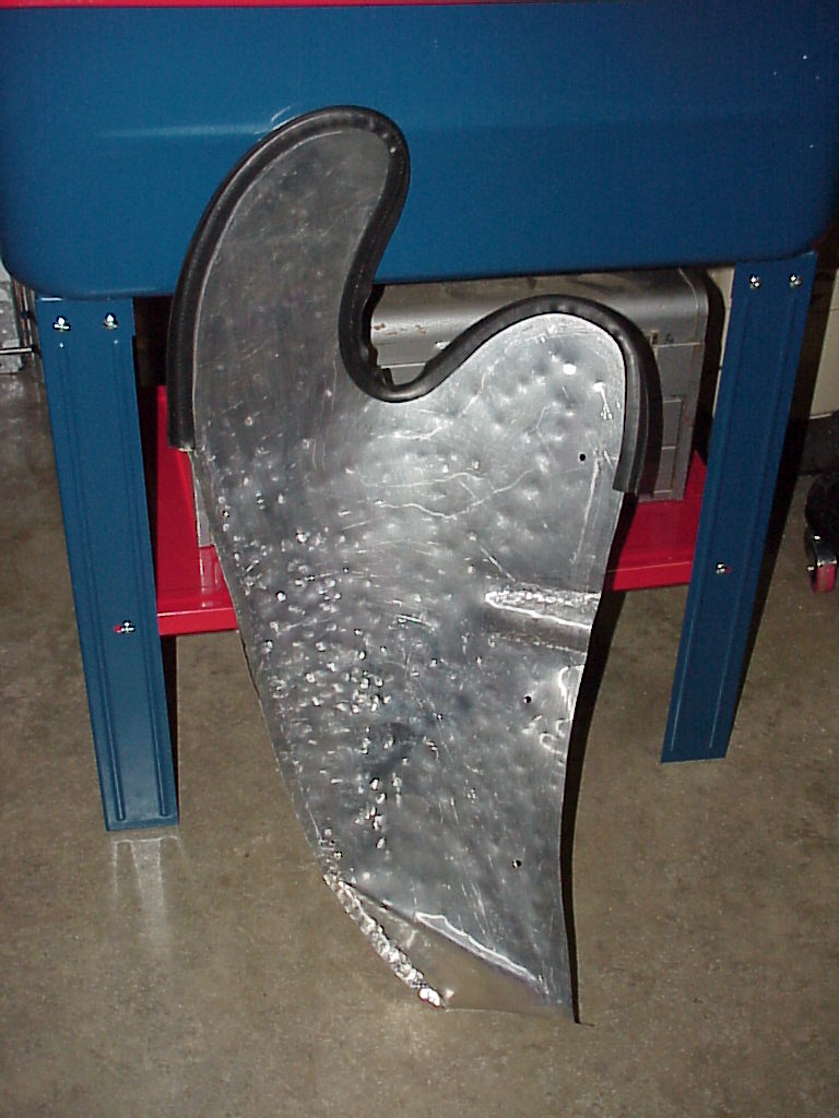
I cut some plywood to hold the edge flat while I beat the curve into the open area. However, the whole thing ended up curling too much and then tearing. So I gave up on that piece. I went back and looked at the replacement piece that came with the car. The curved part was pretty close, so I removed it from the flat steel piece and fit it onto my flat aluminum piece. With some more hammering and cutting, it (right) ended up being quite close to the one (left) from Lowell Brown's car.
I had originally started making the right rear splash shield as a mirror image of the left one. However, the passenger foot compartment is different shape from the driver's side, so I ended up cutting out too much material. To get the right shape, I removed the one from Lowell's car to use as a pattern. However, when I did so, I found about an inch or so of sand and dirt packed in the bottom of the fender area.
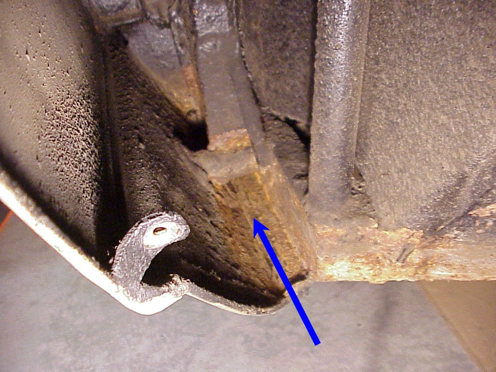
You can see the rusty area pointed out by the arrow. I did remove all of the debris and vacuum out that area, but I'll let Lowell decide how he wants to clean and protect the metal. For anybody with a 330 GT, I strongly recommend removal of the rear splash shields (behind the front tires) and cleaning and rust proofing as needed.
As a side note, Lowell had to have this area worked on a couple years later.
Another thing I had noticed on Lowell's car was a strut that supports the top of the front splash shield. These were missing from my car.
So I had a couple of more parts to make. Here's some pictures from the bare metal to the final strut welded in place ready for painting.
 |
 |
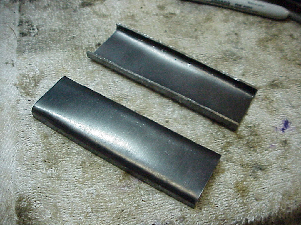 |
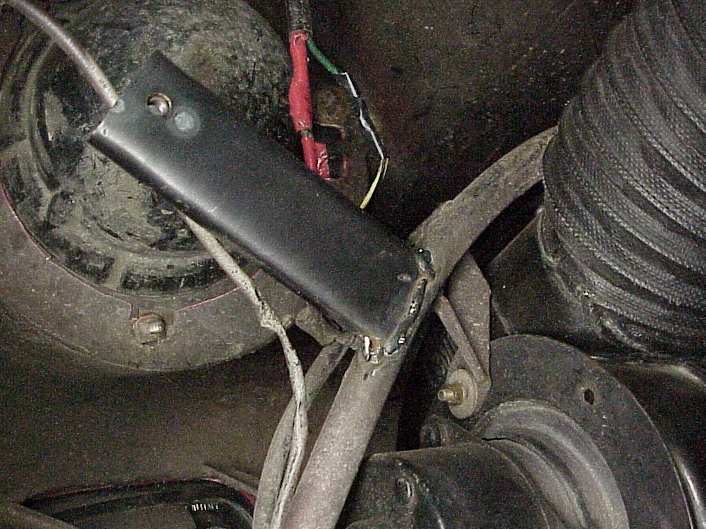 |
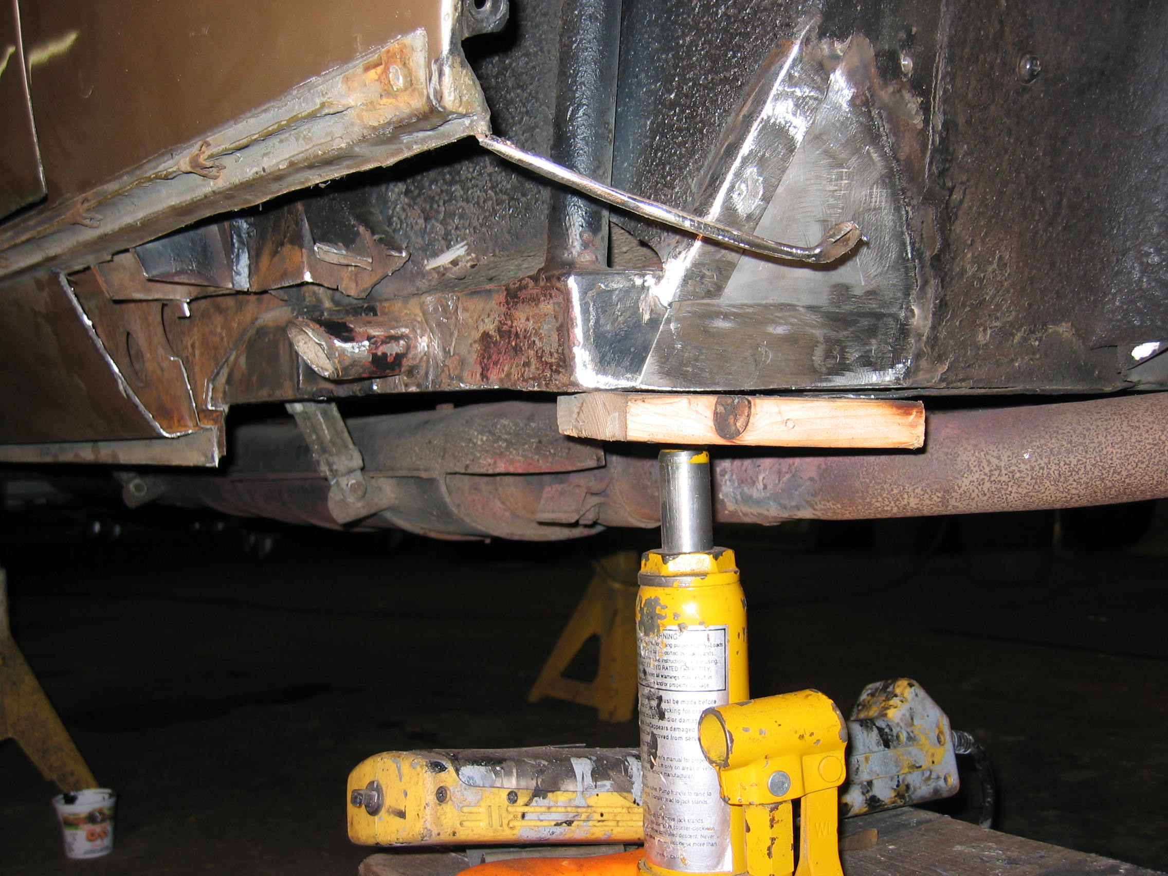
Now that all of the underlying parts were complete, I could install the front splash shields but first I had to fix some problems with the heater vent hose.
I had done quite a bit of work on the rear splash shield but when I went to do a test fit, I found that my mirror image of the left side wasn't correct for the right side. The left (driver's) side has a cut-out needed to clear the area where the brake booster and master cylinder fit into the wheel well. The right side doesn't have that cut-out.
|
|
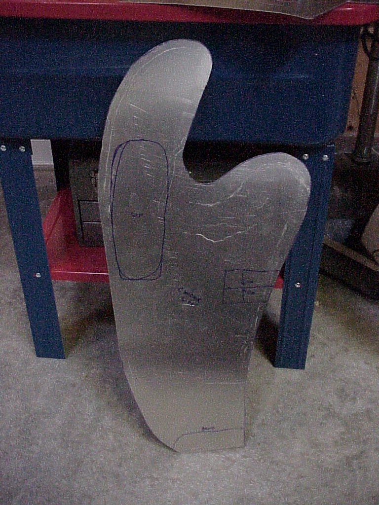 |
In particular you can see the notches in the panels on the left and where the one isn't notched on the right. The one on the right was cut from a tracing based on Lowell's right panel. It's obvious that the 'sign' panel on the left was also made as a mirror of the left side one rather than from an original. One of the interesting detail is that two of the screws go into a threaded piece of steel riveted to the back of the panel.
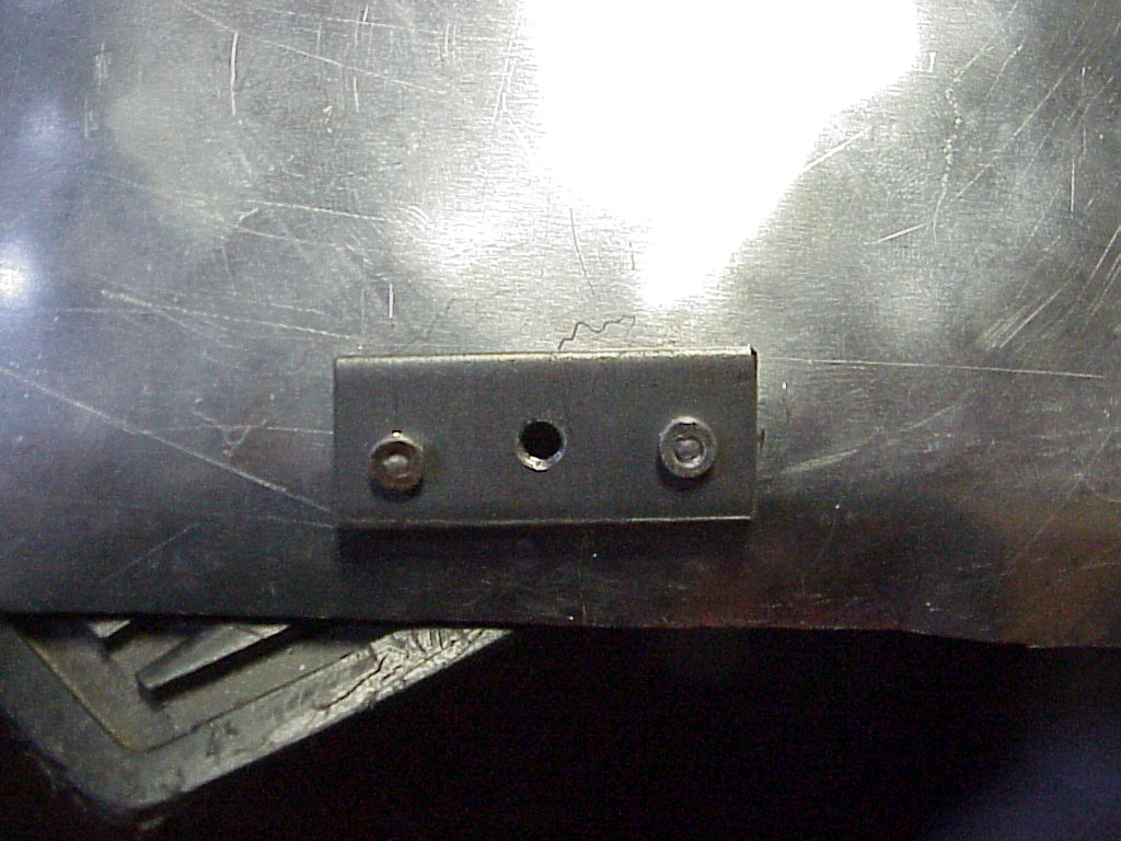
The other three screws go through the panel into similar steel pieces that are spot welded to the body sheet metal. One of the problems was to locate exactly where the holes needed to be in the panel. I ended up using short sections of 4mm threaded rod that I ground a sharp tip on. Then I screwed the rod into the body leaving the sharp end just sticking out. By positioning the panel and then tapping around where the hole should be, the tip left an indentation in the panel so I knew where to drill the hole.
After many trial fittings while I continued to shape and trim the panel, I finally got it fitting correctly. Here it is ready for the final fitting with the rubber seal attached.
The original panels had a large bulge about where the vent area on the side of the fender is. I had thought that the bulge was required to clear the vent assembly, but it wasn't needed at all. So I left it out as it caused major problems when I did the mirror image panel that I couldn't use.