Oil Leak
I've been noticing an oil leak from the front of the engine. It was clear that some was coming from the front main seal, so I replaced that recently.
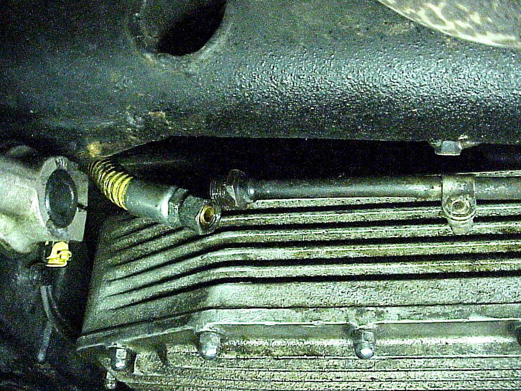
Once that was no longer leaking, I noticed that the bottom of the mechanical fuel pump always seemed to have oil on it. Looking up higher didn't show any likely candidates for dripping down on the fuel pump. The design of the fuel pump is that there is chamber between the seal to the engine (oil side) and the bottom of the diaphragm (fuel side). This chamber should be empty and has a vent hole to allow air to flow in and out as the diaphragm gets pushed up and down. I cleaned the fuel pump and then checked it after another drive or two.
Then it was clear that the oil leak was coming from the vent hole. As the car is on the lift for the A/C work, it made sense to fix this leak at the same time.
Removing the pump was interesting. First I removed the fuel line on the output side. Then I looked at removing the one on the input side. It's in a very difficult place, so I decided to disconnect the far end instead. This is easily accessible as it runs to the hard line along side of the sump.
As I was unbolting the pump, oil started dripping out the bottom, so I knew that I was on the right track.
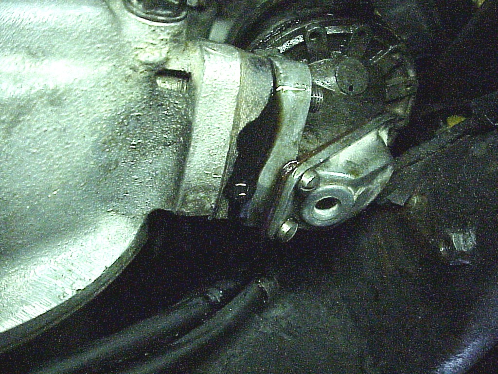
The pump isn't designed to be removed with the engine in the car. There isn't enough room beside the pump to slide it off the studs. I ended up removing part of the pump case (part with the two screws in the picture above) which allowed just enough room to get it out. That let more oil out. Each part I took off (phenolic block and gasket) caused more oil to drip. I just kept the drain tray under where I was working.
Then I looked where the rod comes out and took a look at the parts book.
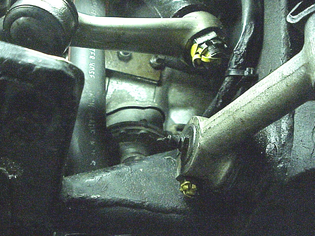
The rod has a mushroom end on the far side that rides on the cam built into the oil pump. There is a brass guide that is probably pressed into the timing case. One O-ring is inside of that guide as you can see from the guide on my PF coupe engine (which is apart).
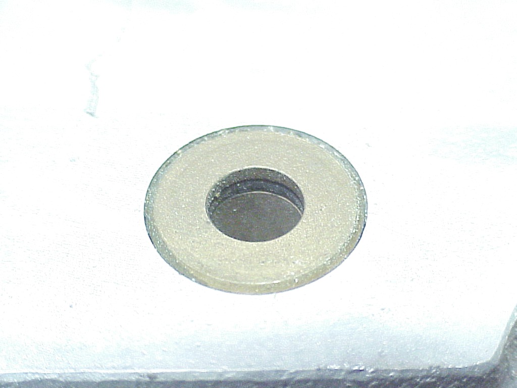
I think that the other O-ring is around the guide sealing it to the case. In any event, the guide needs to come out in order to remove the rod so one can replace the O-ring. At this point I am stuck. I tried putting a pair of vise grips on the end of the rod and using it like a slide hammer to pop out the guide. Nothing happened except that the vise grips eventually slipped of the end of the rod.
I just can't believe that Ferrari designed this so one has to remove the timing case in order to replace this O-ring. I'm going to post a note on tomyang.net to see if some other people have solved this problem.
A couple of people on Tom's message board said to use a dowel pin puller. Snap-On and Mac Tools both have them on their websites. Pretty pricey for a full set, but Snap-On sells the individual pieces. I just needed a 8mm collet and housing. These screw onto a standard slide hammer with a 5/8" SAE thread.
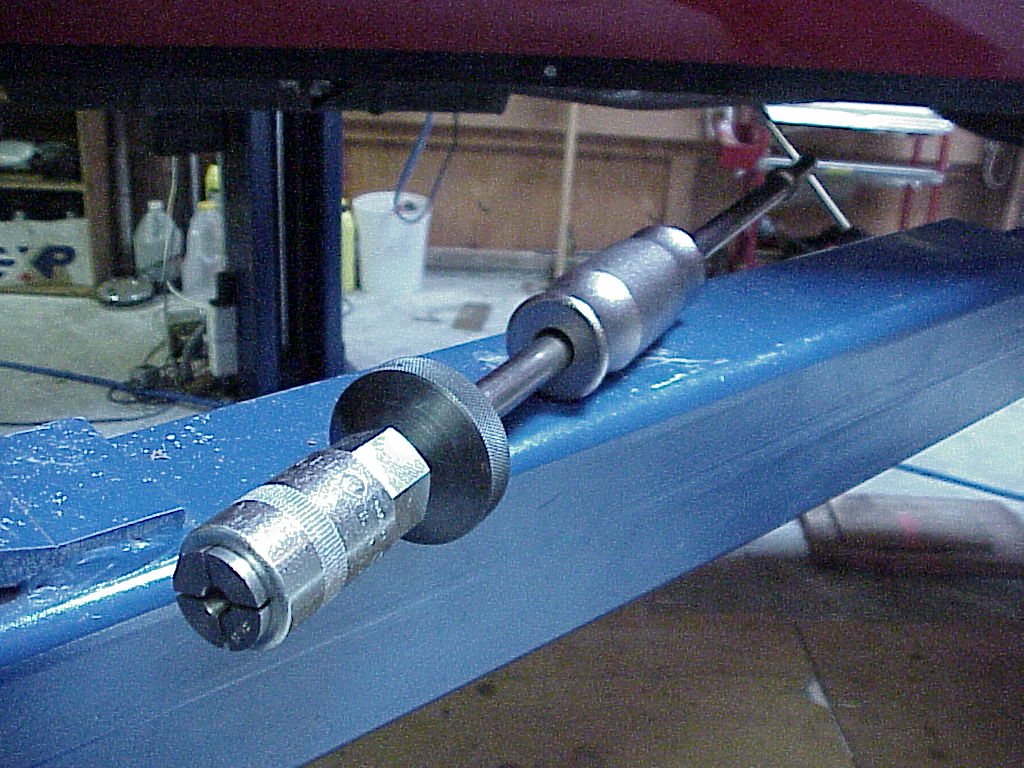
The large knurled ring hit on the frame, so I had to use a regular nut to tighten the collet onto the fuel pump rod. Another suggestion was to put a little fine valve grinding compound on the rod to give the collet a better bite. I had pushed the rod completely in so the grip area was not part of the surface that slides into the bushing.
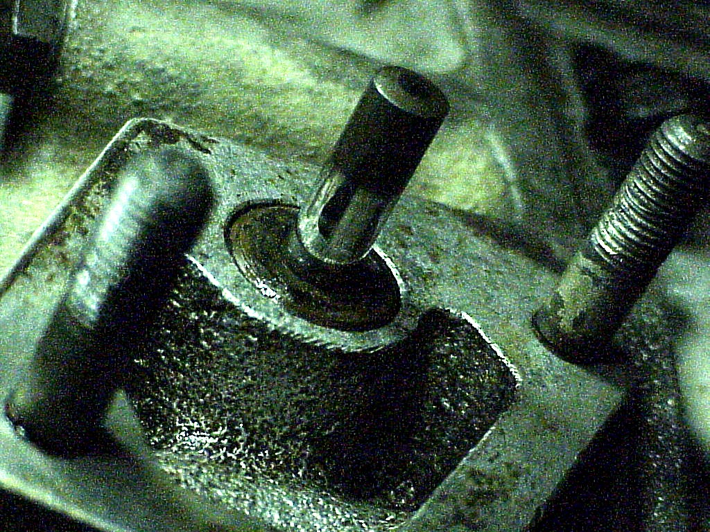
A few taps with the slide hammer part and the bushing started coming out. Here you can see the bushing partially removed.
.JPG)
It was at this point that I remembered that no one had answered my other question. Is this directly connected to the sump, i.e. will lots of oil come out once the bushing was removed? With that unknown, I thought it best to drain the oil. Since I recently changed it, I cleaned the drain tray so I can reuse it. Here you can see the bushing removed and the outer O-ring that seals the bushing to the timing cover with the mushroom head of the rod on the right.
.JPG)
Now I need to get the proper O-rings. Another caveat is that the inner O-ring is easily cut when pushing the fuel pump rod through the bushing.
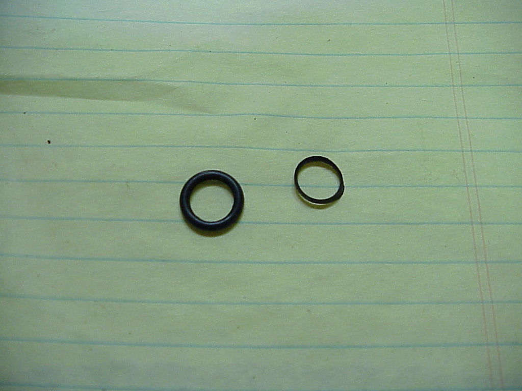
I measured up the O-rings and came up with 11mm x 2mm for the outer one and 8mm x 1.5mm for the inner one. I found that I had an outer one in my spares. I ordered up the inner one from McMaster-Carr. Actually, I ordered 25 of them as that is what comes in the package.
When the O-rings came, I put one in the inner groove and slid the fuel rod through it. Almost no resistance at all. I re-checked the size and found that I had not made a mistake. So I measured the gland (groove) sizes and spent some time looking at what size should be used for that gland. Actually the information works the other way, the size of the gland is determined by the size of the O-ring. Anyway, I came up with 8mm x 2mm as the calculated size. So another order went into McMaster-Carr. At least they don't have a minimum order and the shipping is quite reasonable. I must have used the wrong size when I rebuilt the engine back in 1983. Oh well, live and learn. A couple of extra minutes back then would have saved me a few hours now.
When the larger size arrived, I found that I couldn't get one to fit into the gland. Just too much rubber to go into the small hole and groove. I went back to the internet looking for an intermediate size. After a while I realized that the US size of 5/16" x 1/16" was in the middle. I stopped by an auto parts store and picked up three of them.
| Size | ID mm | CS mm | OD MM | ID " | CS " | OD " |
| 8mm X 2mm | 8 | 2 | 12 | 0.315 | 0.079 | 0.472 |
| 5/16 X 1/16 | 0.313 | 0.063 | 0.4375 | |||
| 8mm X 1.5mm | 8 | 1.5 | 11 | 0.315 | 0.059 | 0.433 |
The ID was just enough smaller so it felt tight around the shaft and I could get it installed.
You do have to be careful when you put the rod through as it's possible that the O-ring can get cut. Another thing I did was to polish the rod to make sure that there were no cuts or abrasions where it slides on the O-ring.
.JPG)
I was a little worried about the OD being too small so the oil could leak around the back side. I put a little silicone rubber in the groove, but then couldn't get the shaft through the O-ring without slicing a small section from the inside. Scratch one O-ring.
I removed most of the silicone rubber and tried again. Another neat circle of O-ring sliced off. You couldn't get such a nice cut if you needed to. I ended up removing all of the silicone and using the last O-ring. I knew that this would work as I had tried this originally.
Then I tapped the assembly back into the front case and installed the fuel pump. As expected, I had to put the pump on and then add the side cover in order to clear the frame member. But everything is back together and I should not have an oil leak there anytime soon.
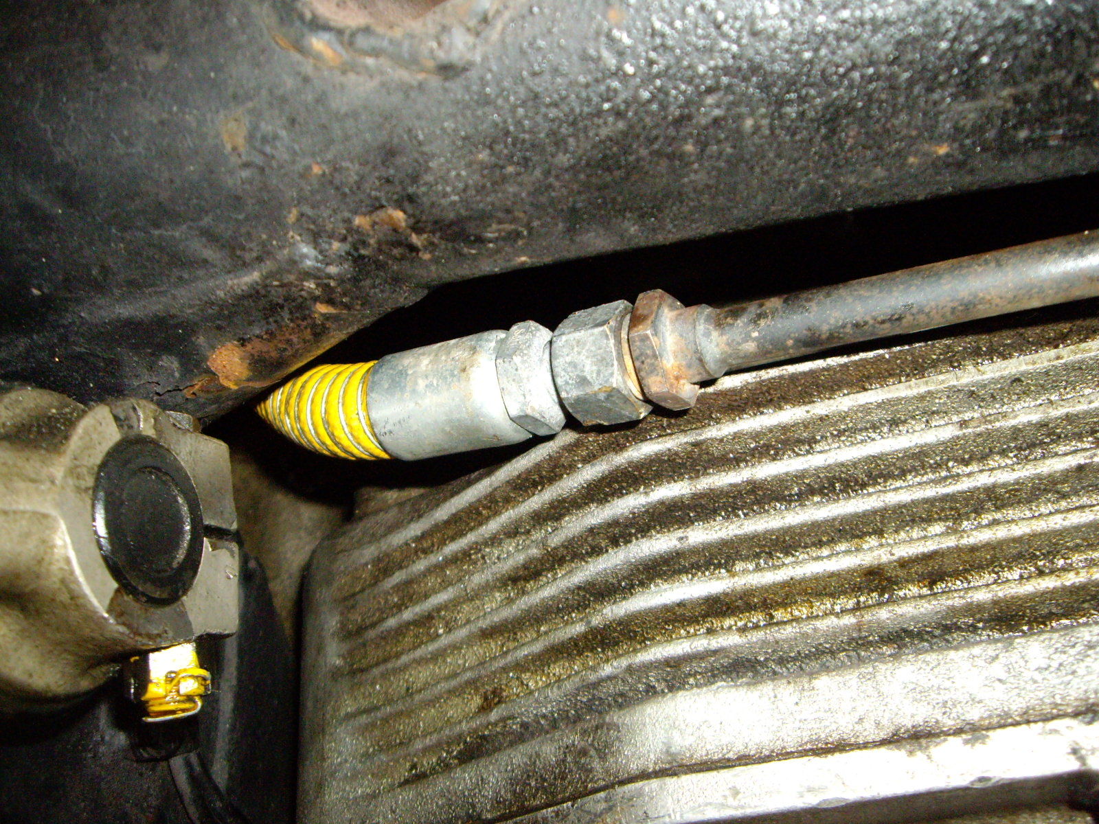
Well, there was no oil leak, but in the process of having to remove one of the yellow fuel hoses, it developed a leak. This was the end where the metal pipe goes to the yellow hose leading to the mechanical pump. It was leaking from where the fitting screws into the hose. I think that I inadvertently loosened it when I was tightening the swiveling fitting. Instead of the fitting rotating, the whole fitting unscrewed from the yellow hose a little.
One issue was that the fuel tank was pretty full, about 17 gallons in it. I really didn't want to drive it around with that leak being quite close to the exhaust. I recently changed the electric fuel pump in the 308, so its tank was pretty empty. However, it's not as simple as draining from one to the other. I have a 5 gallon drain pan with a nice pour spout that fits into the rolling adjustable oil drain. So, with the help of my wife, I removed the drain plug and let about 3 gallons into the pan. Then I stuck a finger or thumb over the hole while she emptied it into another (one of several) container. Then we repeated the process until the tank was empty. The various containers where then emptied into the 308 except for a 5 gallon one. Then I was able to open the fuel line and remove the yellow hose section that was leaking. Once off, I slid a section of 3/4" PVC pipe over the yellow hose and clamped one end in the vise. Then you can tighten the other end without having the yellow hose trying to twist up. Others use a split piece of wood to clamp the ferrule and hose, but I find my way works just fine. In addition, both ends get tightened at the same time. Once I had it tight, I put everything back together and tested with the saved 5 gallons of fuel. No leak anymore!
I also noticed a slight leak at the outlet of the mechanical pump where the banjo fitting bolts on. Since the system was dry, I took the opportunity to remove that fitting and anneal the copper washers. These work harden when they are reused. Annealing (heating up with a propane torch and letting cool naturally) softens the copper again so it can seal properly.