Winter Project - Rear Suspension
Lowell Brown (8855GT) recently had his car apart renewing the rear suspension. Even though this is not on my car, I wanted to document the work, mainly so when I get around to doing it on my car, I'll have this as a reference. And perhaps another 330 GT owner might benefit also.
Lowell had been chasing a Ferrari 430 on the curvy high road to Taos, NM with a friend who is an vintage race driver. The friend said that he thought that the rear end felt loose. Then there was a post on Tom Yang's message board talking about how the rear suspension on Yale's 330 GT was in really bad shape. So Lowell took a careful look at his and found that he could wiggle the rear spring bushing with a pry bar.
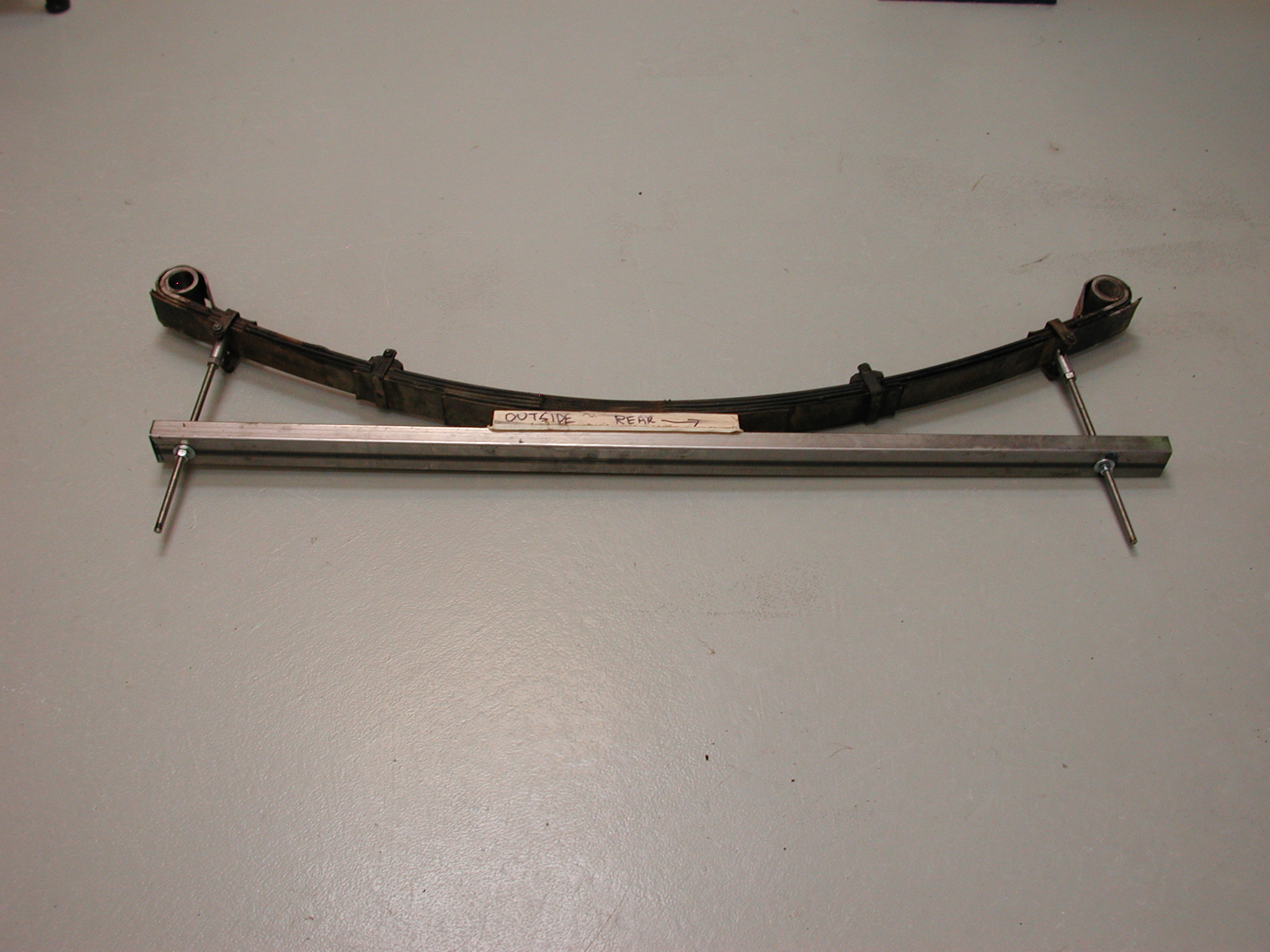
To start he built a spring compressor using some 1x2" rectangular stock and some pieces and bolts to be able to attach the stock to the underside of the spring and using a nut on the long attachment bolts, tension each end of the spring to flatten it as needed.
As you can see, it attaches to the clips that keep the springs aligned near the ends. Parts list:
- 1"x2"x5' rectangular aluminum stock
- Two 3/8"x3' threaded rod, nuts and fender washers
- Two 1/4"x3" grade 8 bolts and nuts
- Two connectors 3/4 OD", threaded internally to 3/8" and with 1/4" cross hole. Custom made.
- Two 3/8" nuts (locking nuts for connectors)
Next was removal of the spring assembly. Lowell started on the driver's (LH) side. As a reference, here is the page from the parts book showing the rear suspension. Items with a number after them in parenthesis refer to this diagram. Note, this is the LH side and the front of the car is to the left.
| This
picture is from tav. 23. The upper radius arm is not shown in tav. 24, but it attaches to the ears above part 29. The leaf spring assembly (27) fits into part 29 and is held in place by bolts (42 and 43). Note, the shock assembly lower end fits onto stud 18. |
 |
The order of removal to replace the bushings and silent blocks in the rear suspension is:
- Exhaust system or at least the rear elements.
- Coil-over spring and shock assembly (5 and 17) as a unit.
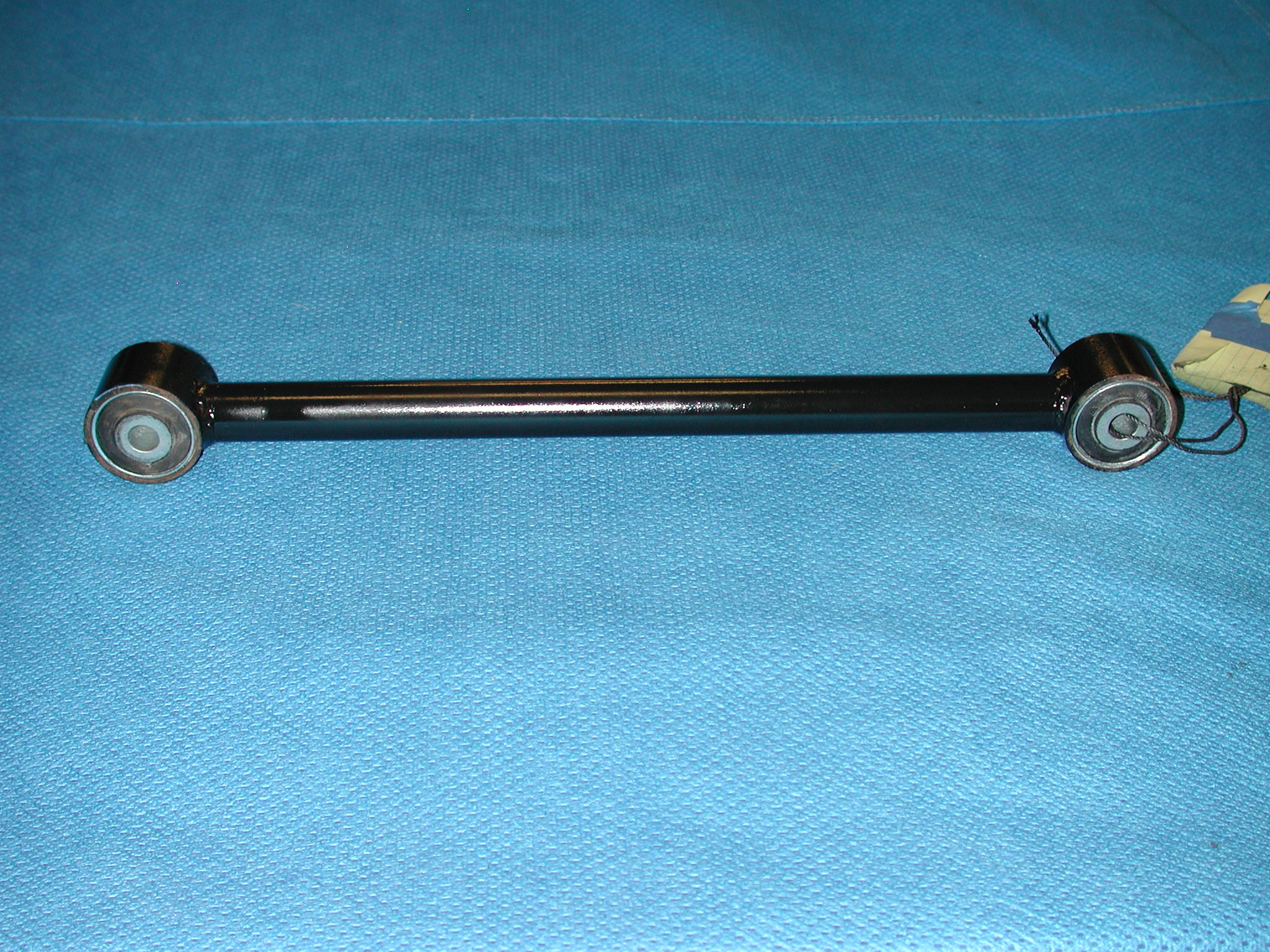
- Lower radius arm (36).
- Lower radius arm fitting (39).
- Spring and shackle assembly (27 and 12) as a unit.
- Upper radius arm (not shown).
The exhaust system on each side has to be removed, or at least the rear half. However, separating the two halves is difficult as they rust together quickly. Similarly, the front half rusts to the collector pipe, so sometimes it is quickest and easiest to remove the collectors from the headers and drop the whole length as a single unit. At some point, the LH exhaust on Lowell's car got mis-aligned and some of the hangers needed extensions to get it mounted. Lowell wanted to address this since he had to remove the exhaust anyway. With lots of difficulty, he separated the front halves from the collectors using heat, a putty knife and a heavy copper hammer to beat on the muffler, driving it to the rear. After this was done, he determined that the collectors had so many holes that they needed replacing, so a set of stainless steel ones were obtained from Timevalve.
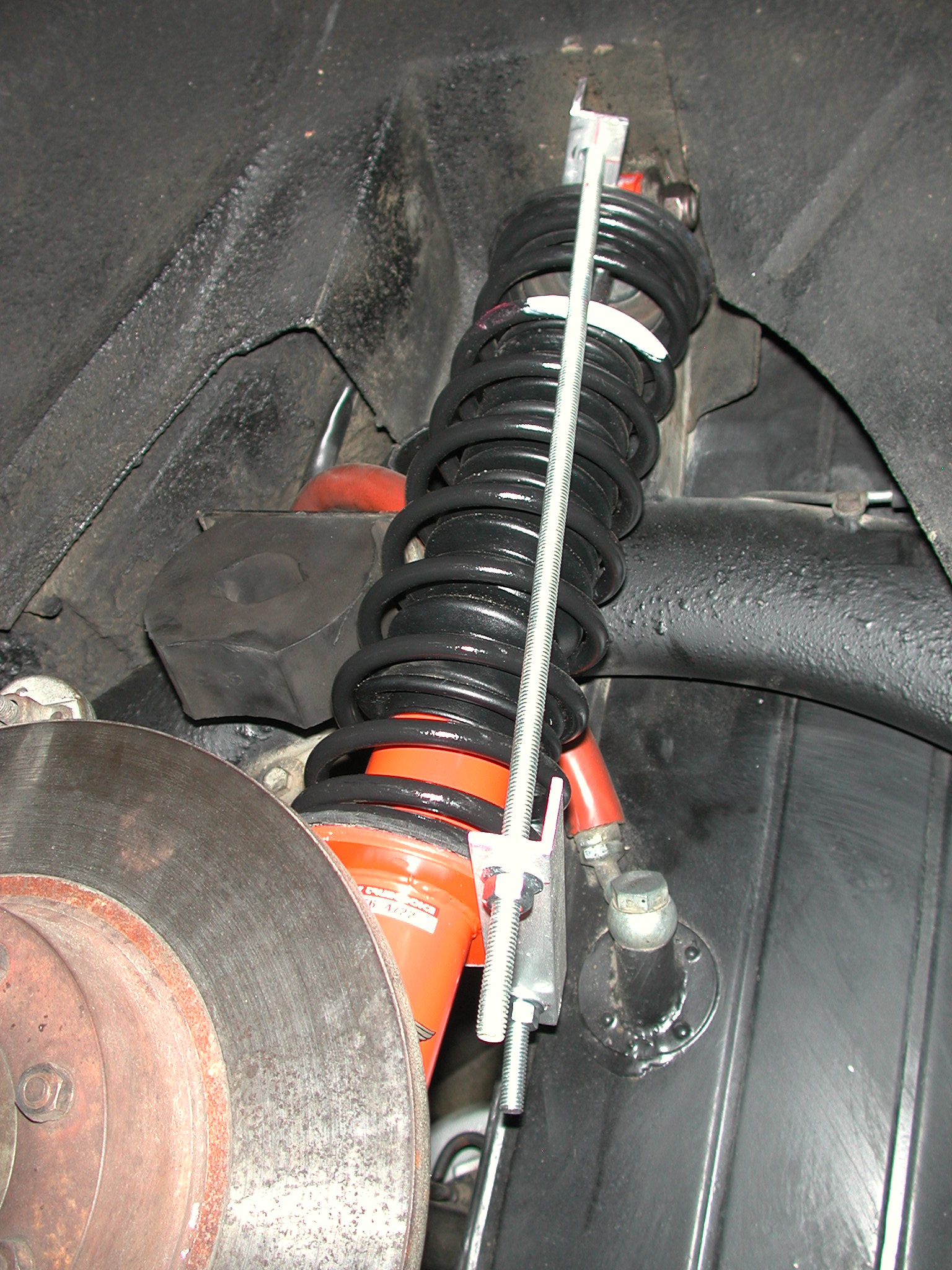
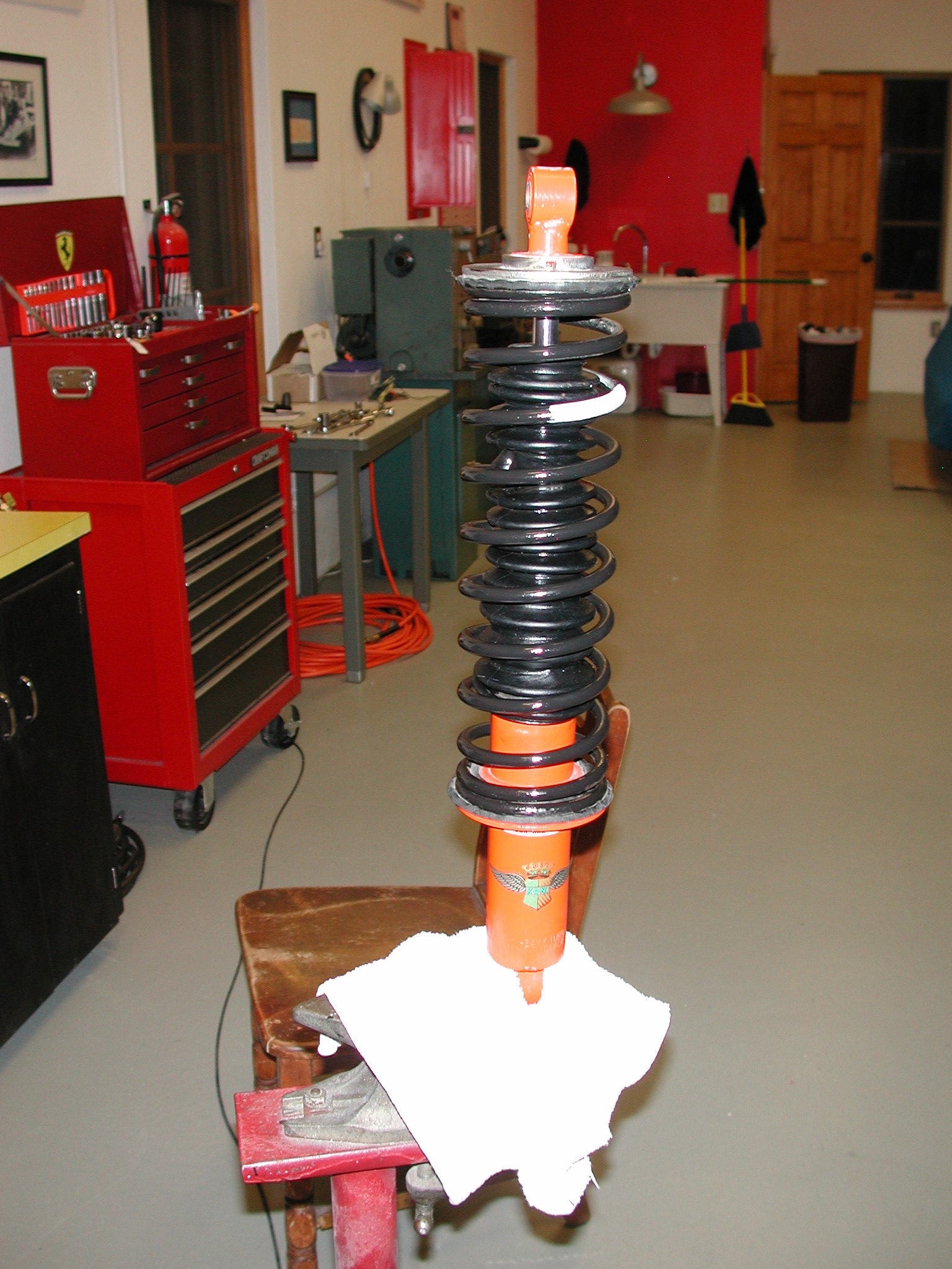
Then the shocks (5) and coil-over springs (17) were removed as a unit. This required another spring compressor to relieve the pressure on the top and bottom bolts.
The lower radius arm (36) was the next to come off. He removed the nuts and the front bolt (33), but he could not remove the arm because the rear bolt (37) ran into the brake disc. Using a socket and breaker bar, he removed the two rear nuts on the fitting (39) that attaches the radius arms to the spring, but he could not remove the two front nuts (41). These do not have sufficient clearance to use a socket, and he could not get enough torque on them with an open end wrench. The bolts were rusted in place in part 29 of tav. 23. After grinding down the box end of a 17mm combination wrench to fit in the space available, one one front nut came off with an extender on the wrench and a lot of force. The other nut started turning slowly, but the bolt (42) was gradually shearing and then broke. At least the radius arm was off. Note, if the bolts can turn, then removal is simpler as the force can be applied on the bolt head and the nuts can just be held in place with an open end wrench. Note, it is not obvious, but there are three bolts 42 (75mm) and one 43 (105mm) as one of them goes through a thicker portion of the fitting (29).
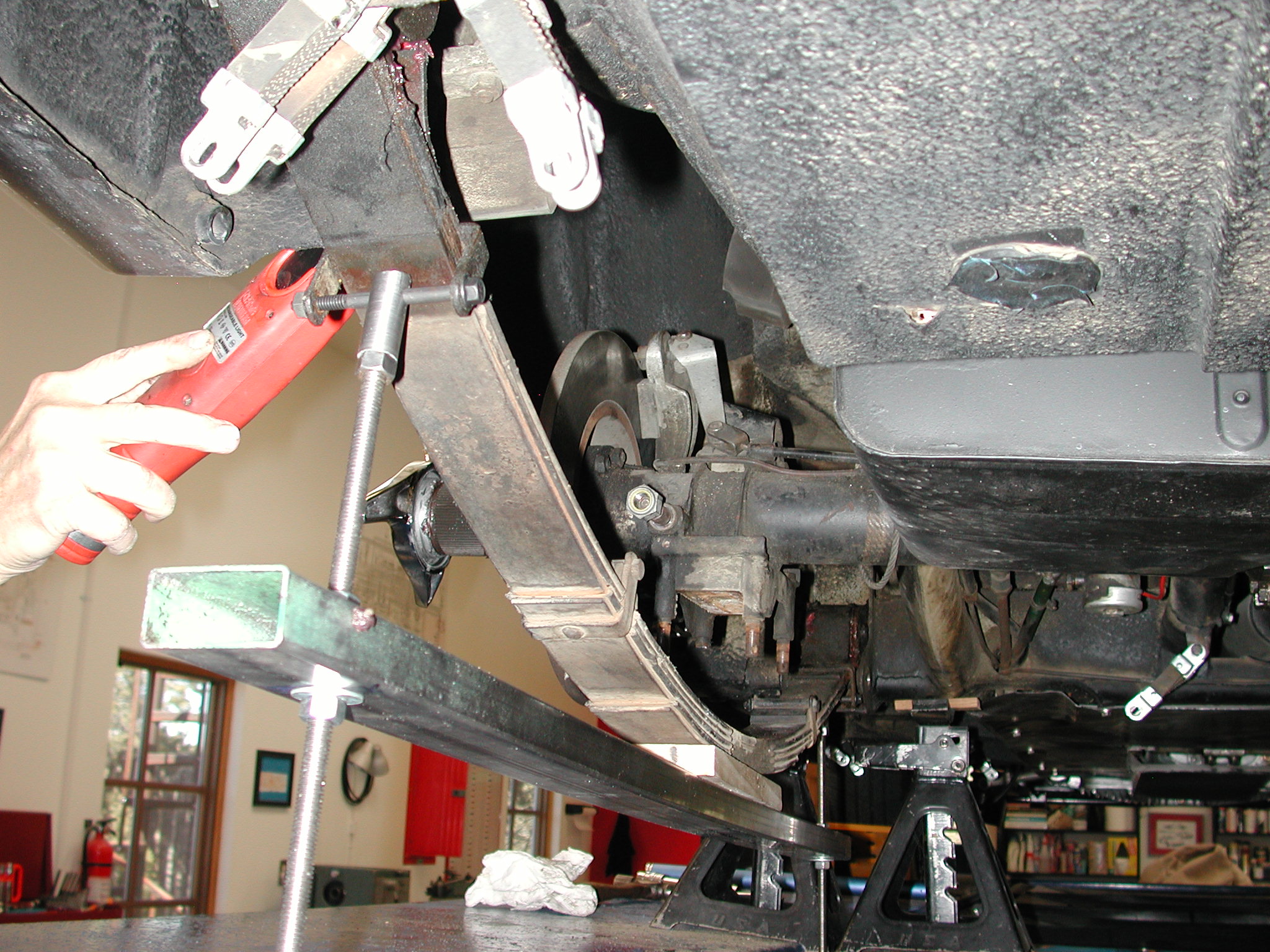
Attaching the spring compressor to the leaf springs requires removal of the bolts and rubber on the clips. Then the 1/4" bolt is put through one side of the clip, connector and through the other side. A piece of wood with a hole drilled to fit over the nut on the bolt (27) that holds the leaves together goes between the rectangular stock and spring.
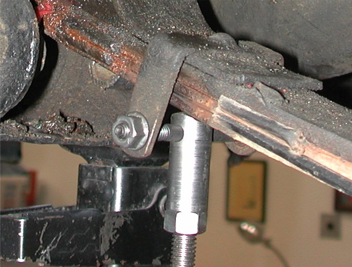
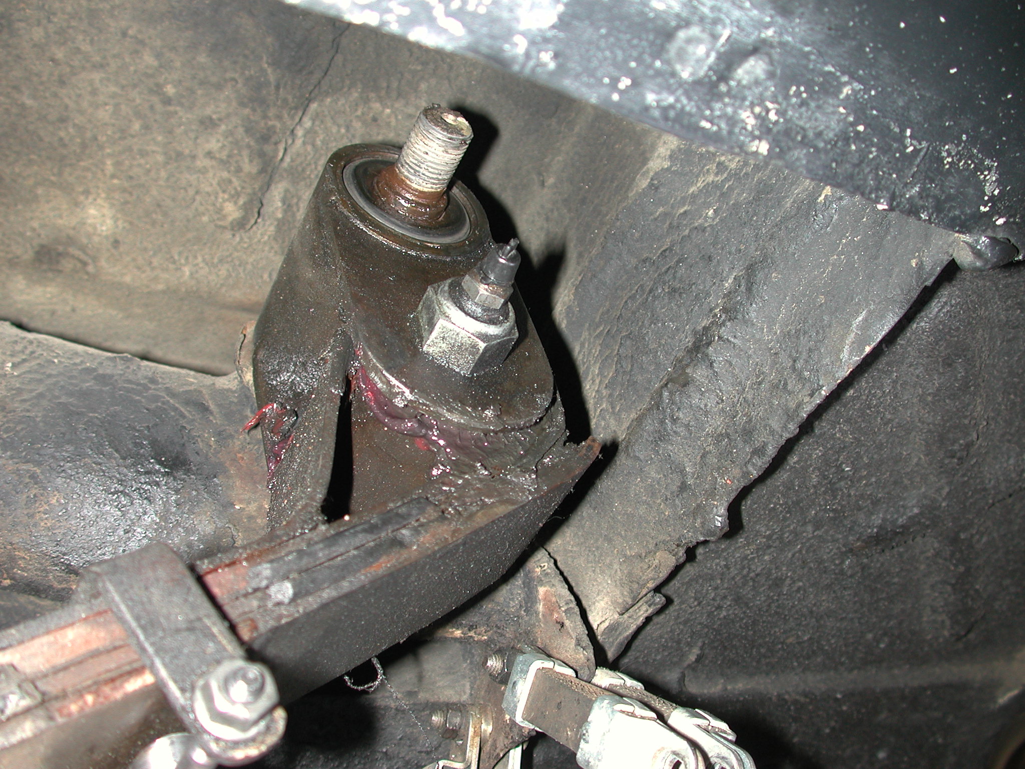
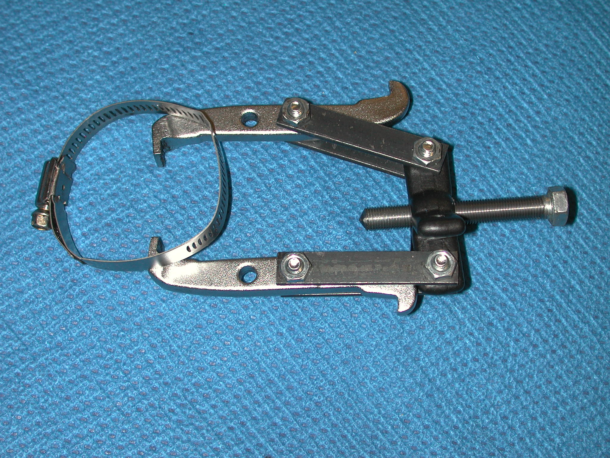
After tightening up the nuts on the threaded rods to partially flatten the spring enough to relieve the pressure on the shackles (12), The front shackle bolt (13) was removed. The rear shackle is mounted on a stud at the top. After removing the nut (14 rear), the shackle and spring assembly would not come off the stud as the inner sleeve of the silent block (11) was rusted to the stud. A pulley puller was purchased and modified with a couple of extensions to fit over the shackle. A longer bolt was also needed. The hose clamp was used to hold the jaws of the puller on the shackle tightly. A larger puller with long enough arms would not have fit in the available space.
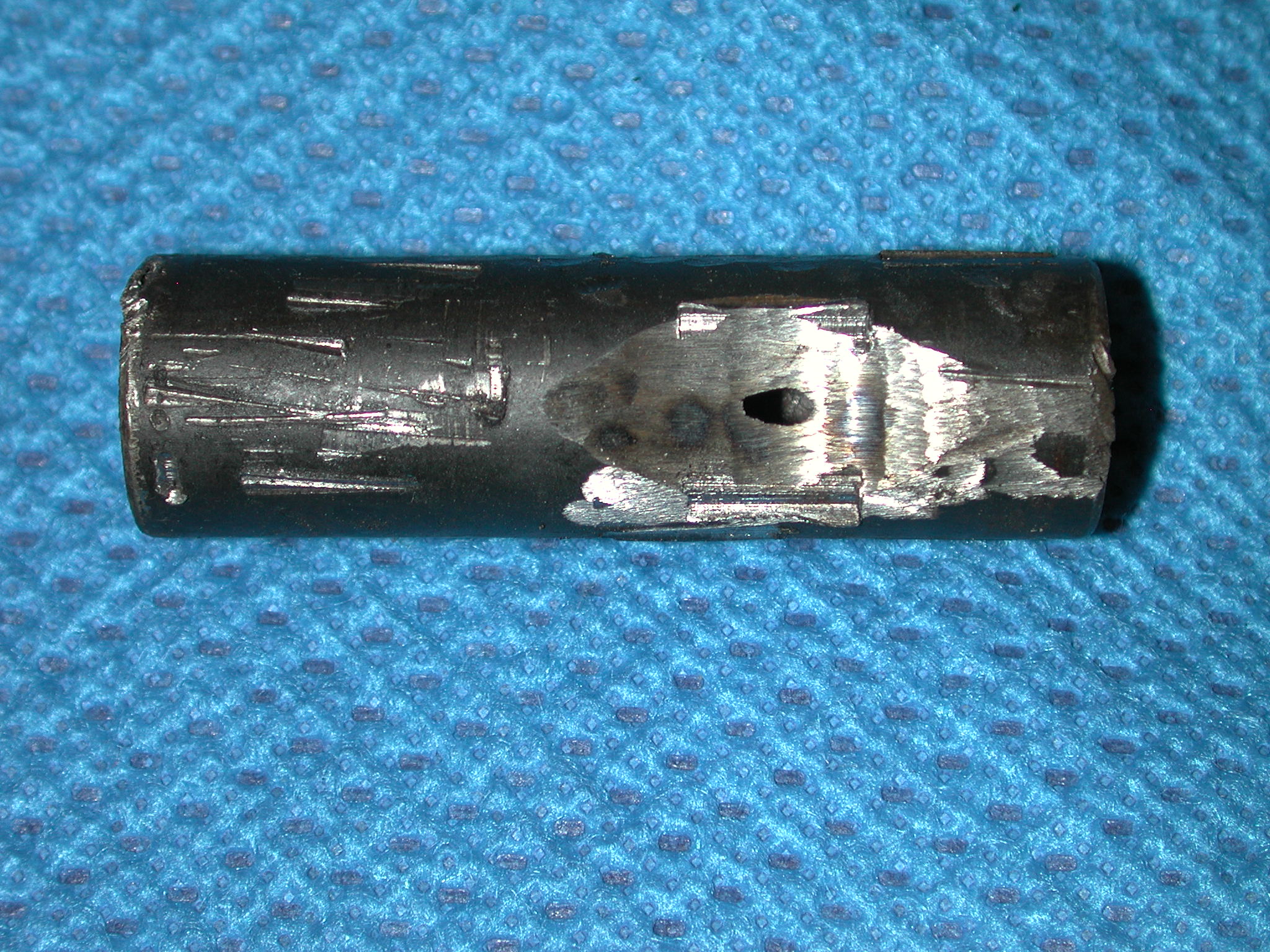
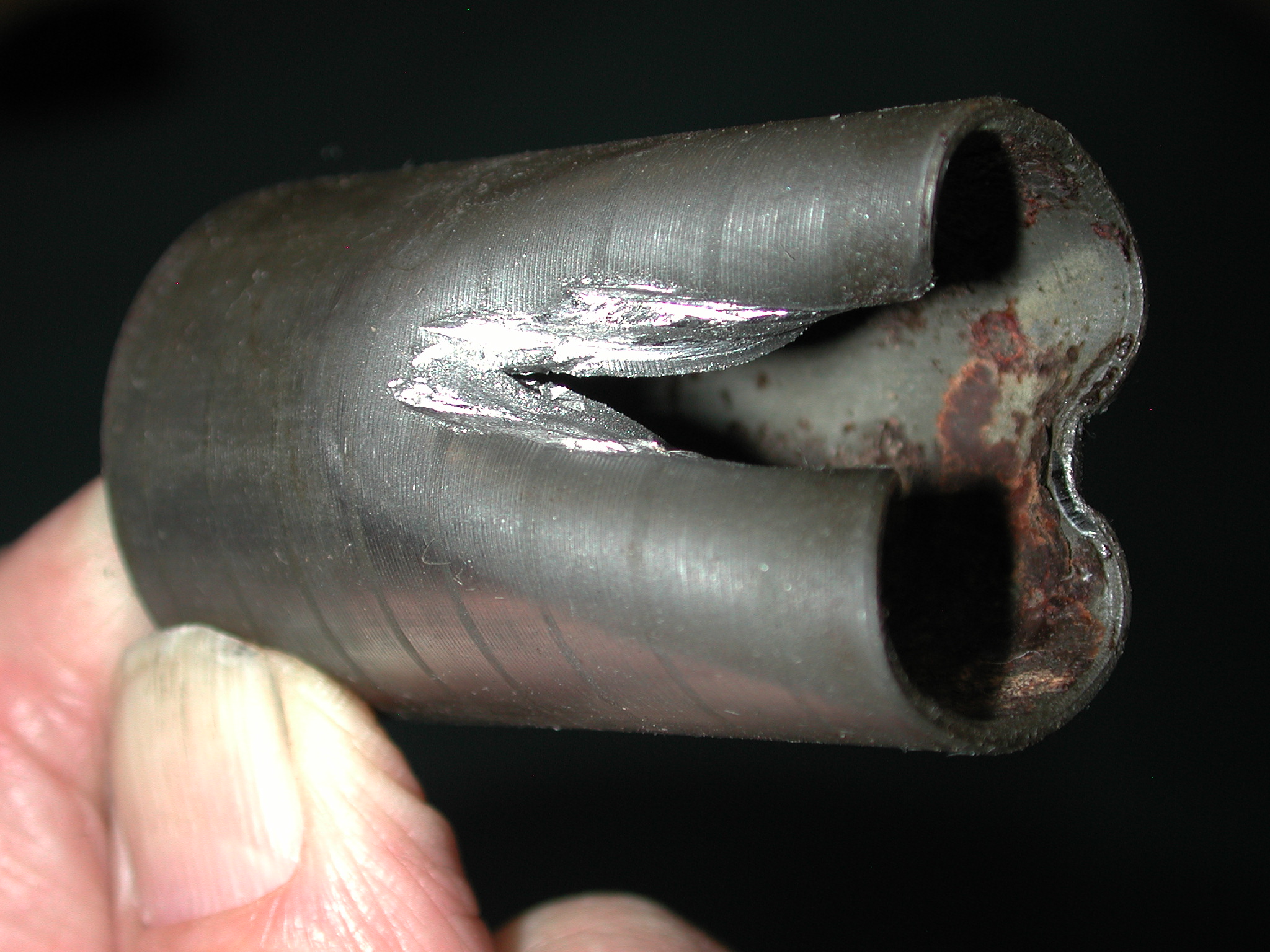
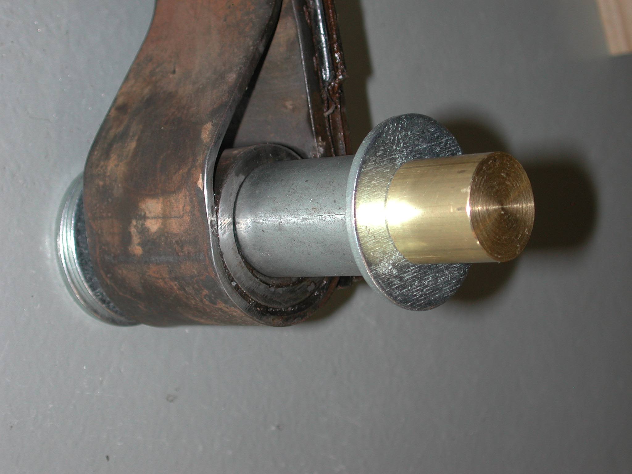
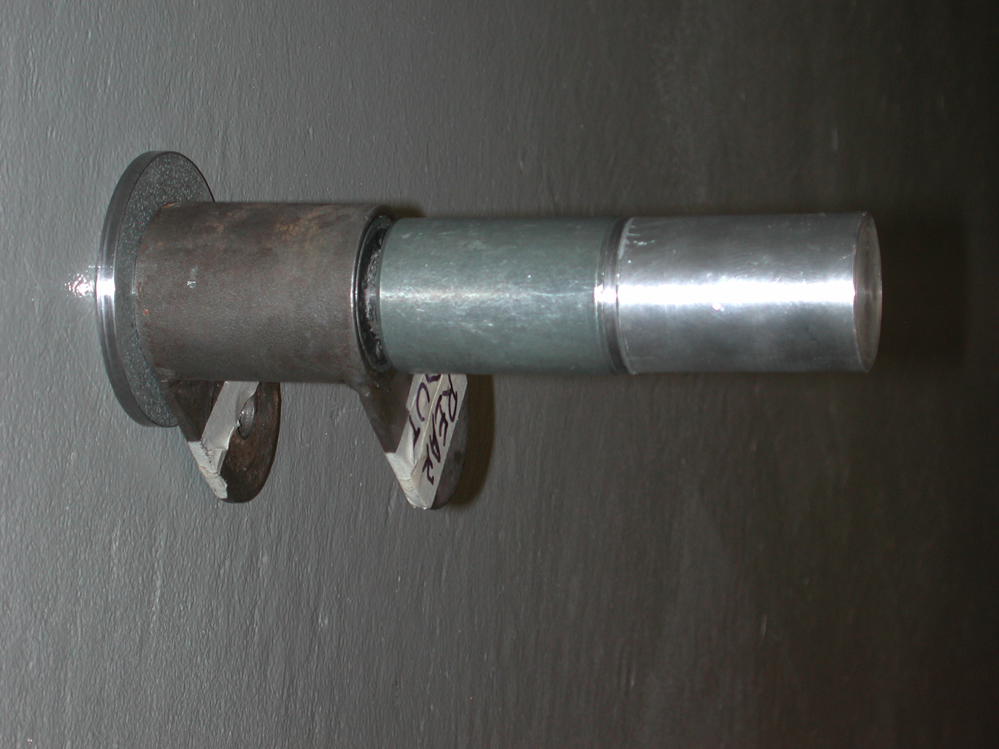
After much effort of the puller and use of a rubber mallet, the shackle and spring assembly came off. However, what separated was the rubber of the silent block. The inner sleeve was still left rusted to the stud. Very carefully, an area was ground down on the sleeve just to the stud. A micrometer was used as this was being done to make sure that the stud wasn't being ground into. Once the stud was exposed, PB Penetrating Catalyst was used to saturate the inside of the sleeve and the stud. Then a pair of Vise Grip pliers was used to rotate the sleeve and work it off the stud. Here is what the sleeve looked like after removal. You can see the small hole used for the PB Blaster.
Now the upper radius rod could be removed.
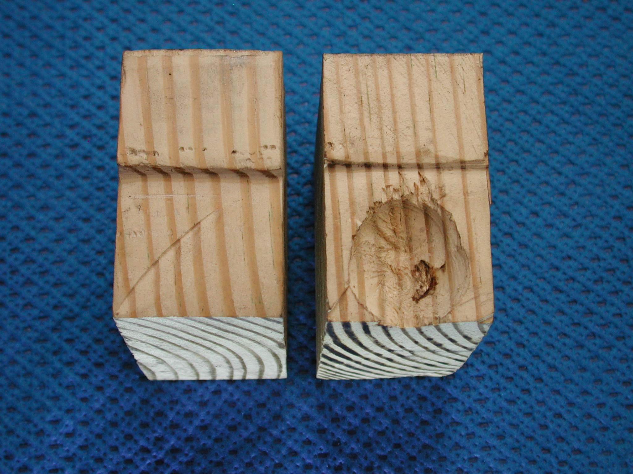
The spring was separated from the shackles. Notice the writing on the wood block denoting its orientation on the car.
After inspection, it was clear why the rear end of the car felt funny to Lowell's friend when he drove it. There was no bushing (20) left, only the inner (22) and outer (21) sleeves. The space just had grease in it. So that end of the spring could move around about ±1/4" without any corresponding chassis movement.
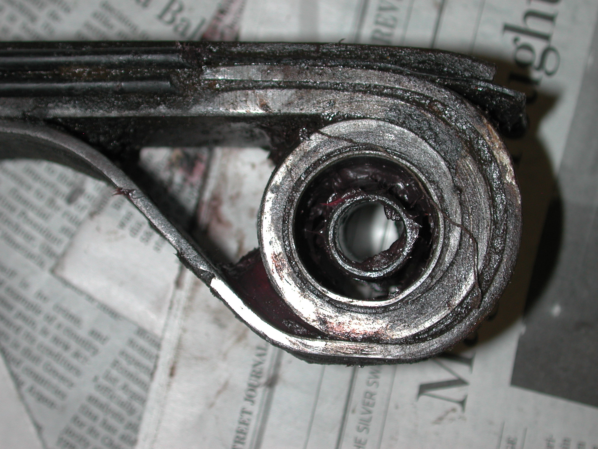
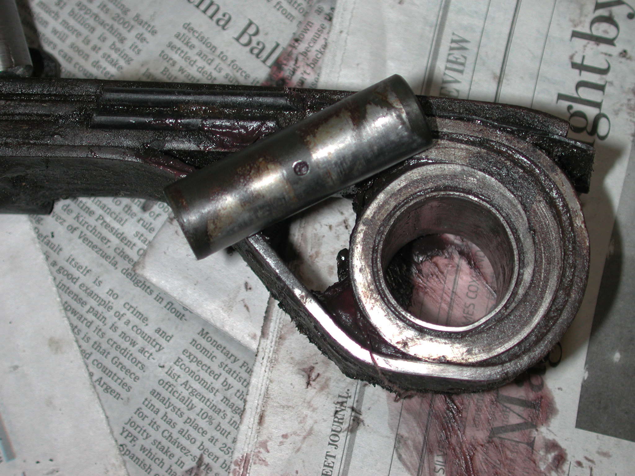
These bushings (20) are not available. The choice is to make a replacement out of hard polyurethane or Teflon material or replace the sleeves with a silent block. Lowell chose to do the latter. Tom Yang did the former when redoing the suspension of Yale's 330 GT. See diary posts on 12/23/2012 and 12/29/2012 for more information.
The outer sleeve (21) was too thin to press out, so it was just collapsed inward with a punch and then driven out.
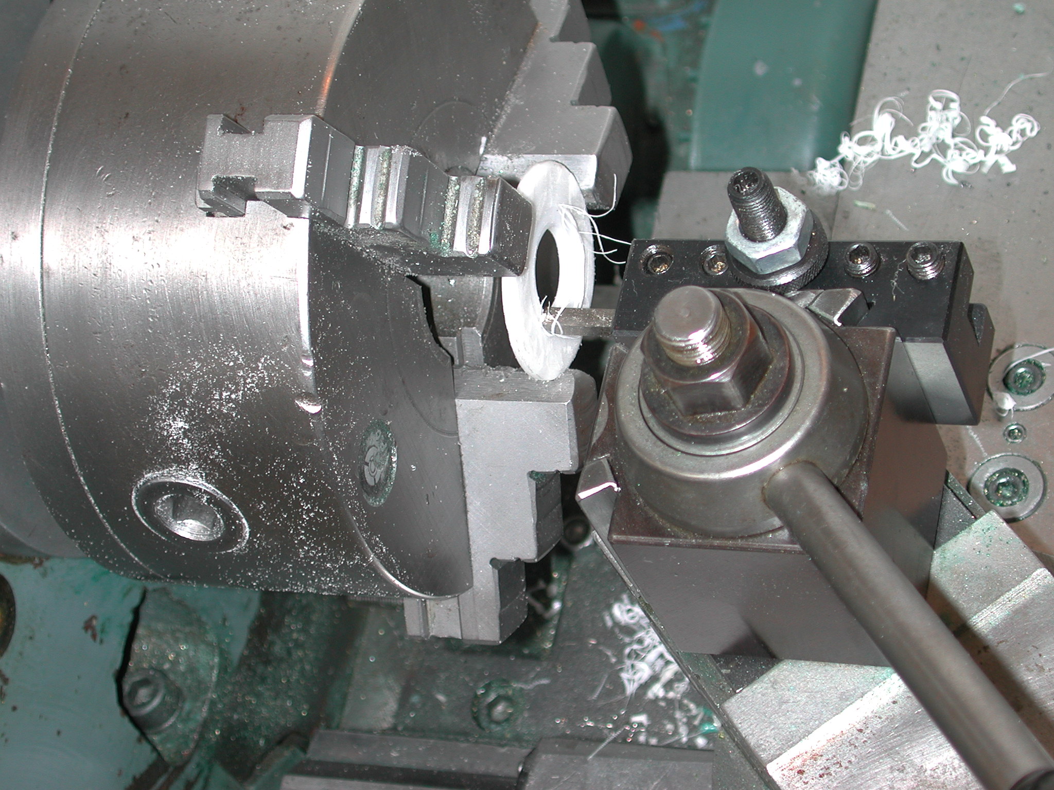
A pusher and washers were made to fit the radius rods to remove the silent blocks. The pusher was made of aluminum as it was available and easily turned in the lathe. In order to prevent the aluminum from deforming, steel washers were sized to just match the OD of the silent block. These protected the aluminum pusher.
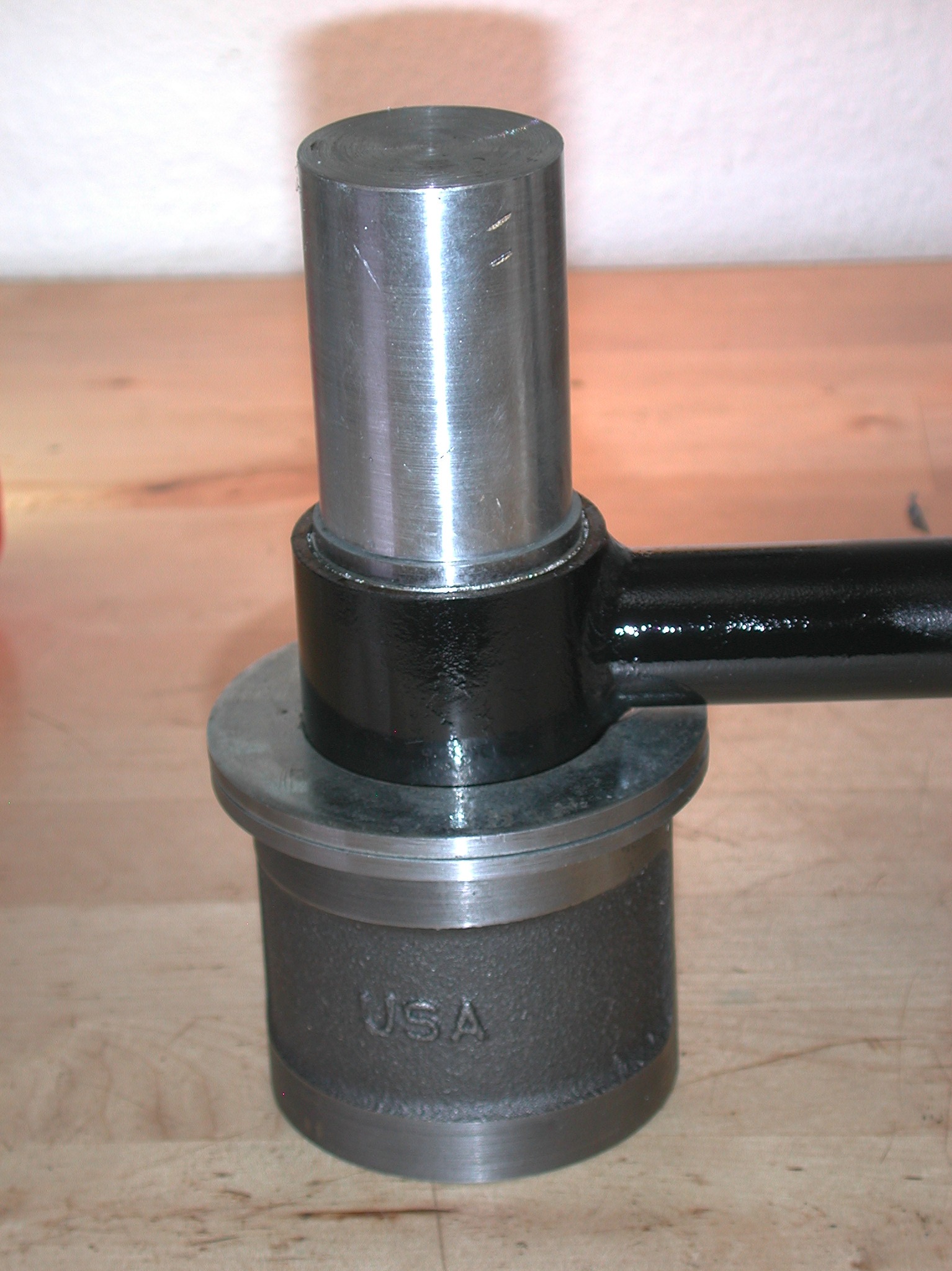
Having a lathe to make the pushers and washers of appropriate diameter was essential.
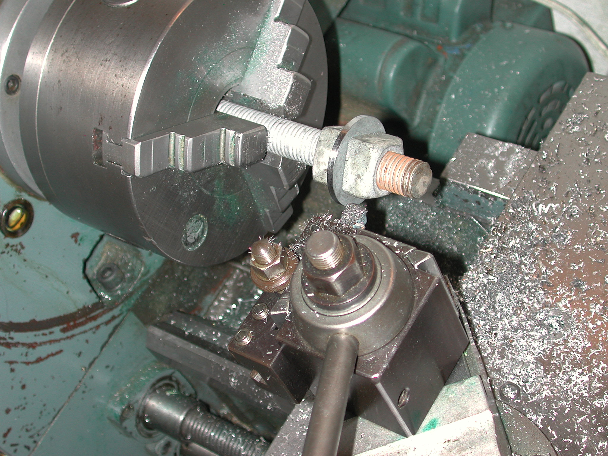
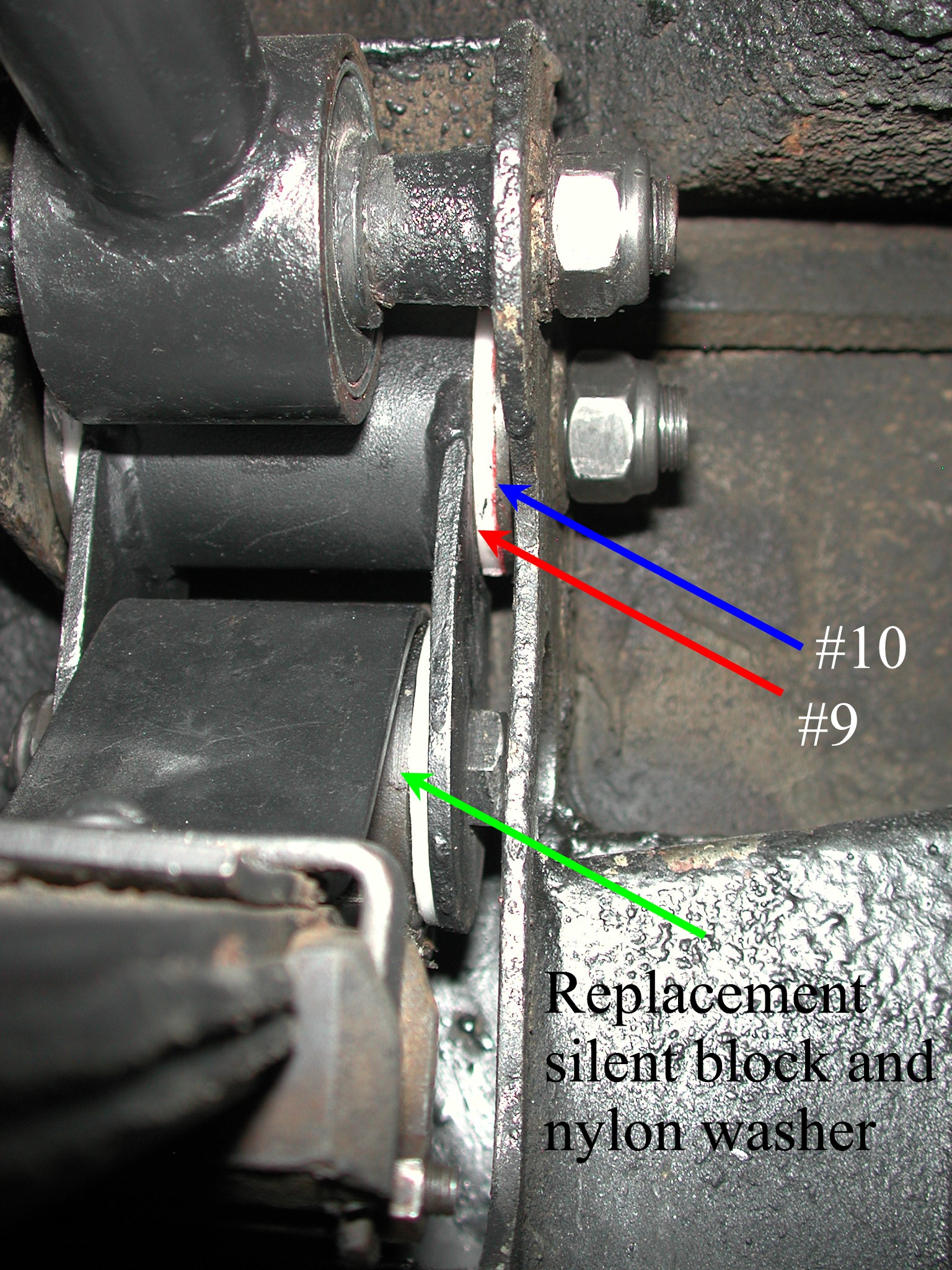
The new silent blocks to replace by spring eye bushing assembly are not as long as the original. Nylon spacer washers were supplied, but they were too thick causing the ears of the shackle to spread noticeably, so Lowell had to use the lathe to thin them down. He found that the tool gouged the nylon with the lathe running, so he ended up turning the chuck by hand. He also relieved the inner hole of the new nylon shackle washers (10) so they fit over the the rubber ends of the silent blocks (11) nicely. Note that the washers (9) have an inner lip that fits inside the nylon washers.
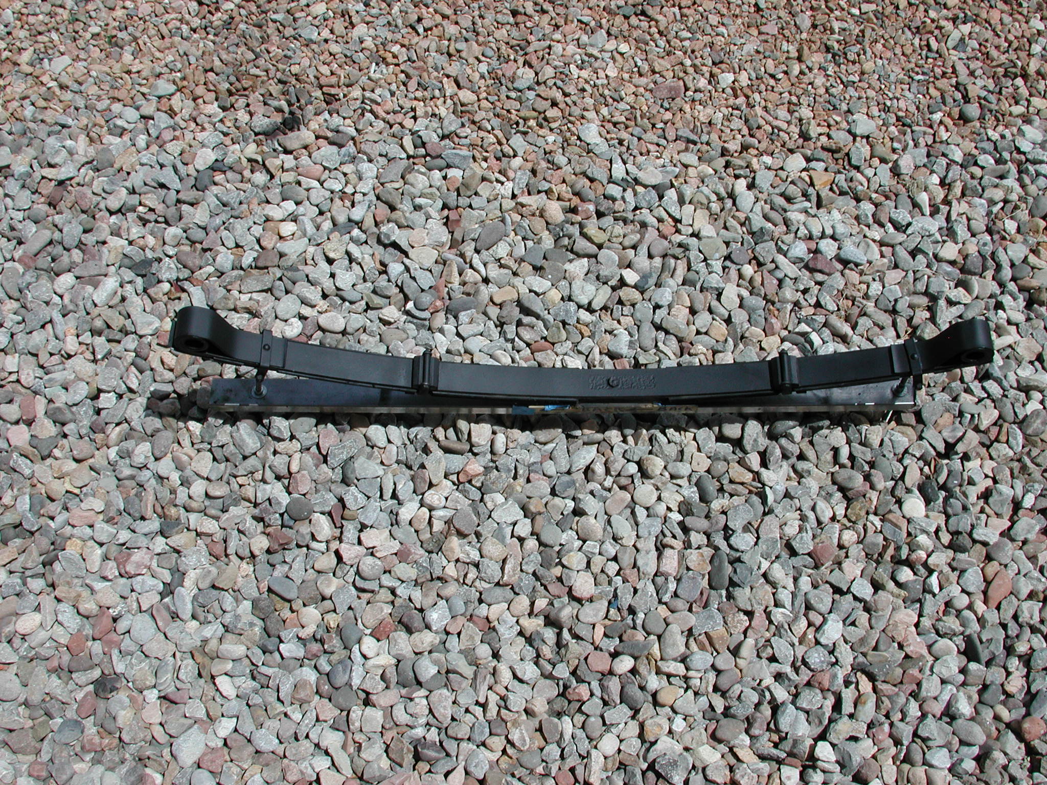
All of the parts were bead blasted and painted.
Pushers and washers were made to allow pressing of the silent blocks into the spring eye, shackle and radius arm.
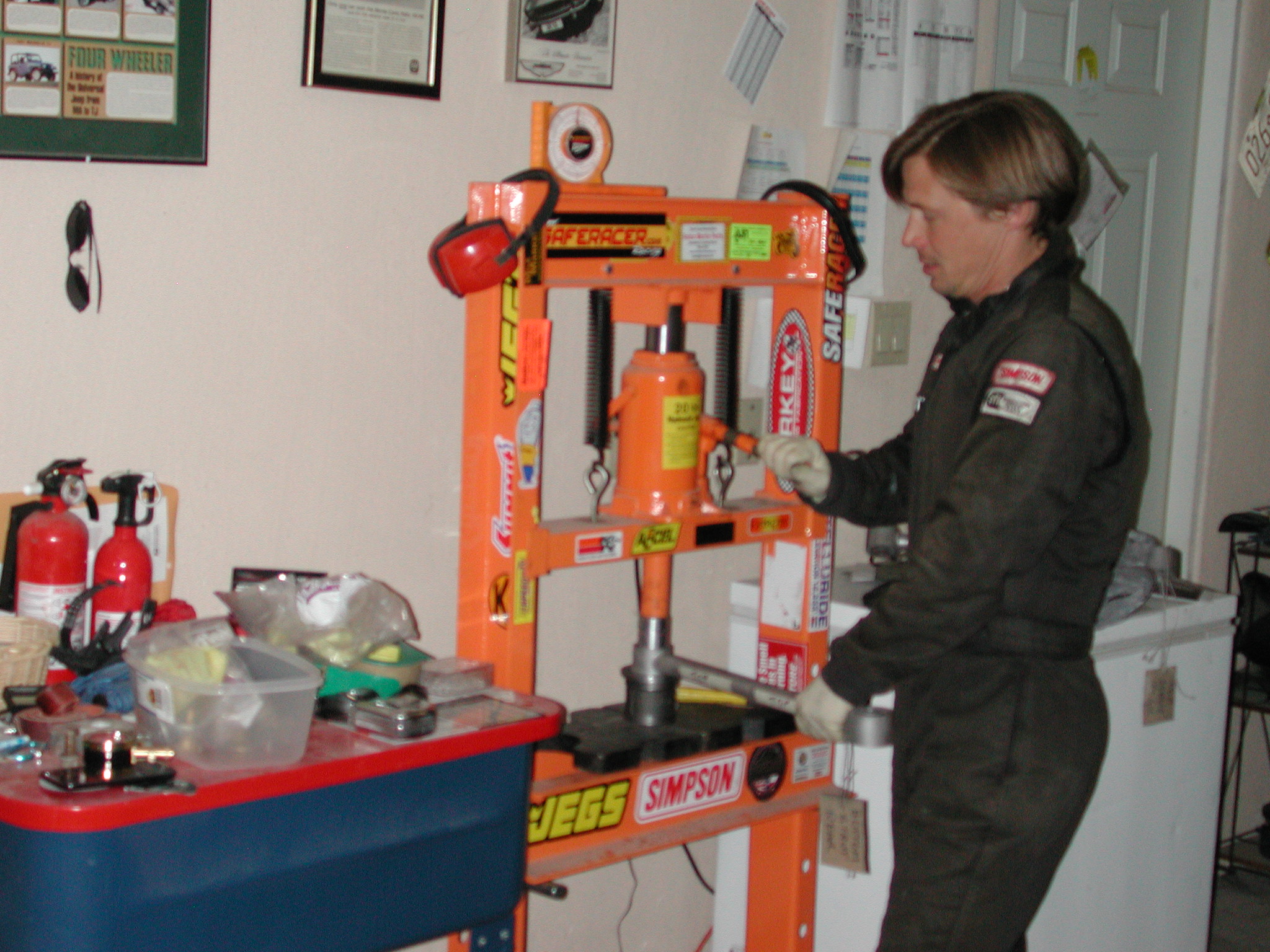
Then the new silent blocks and bushings were fitted using the same pushers. Here is a friend of Lowell's working on a radius arm.
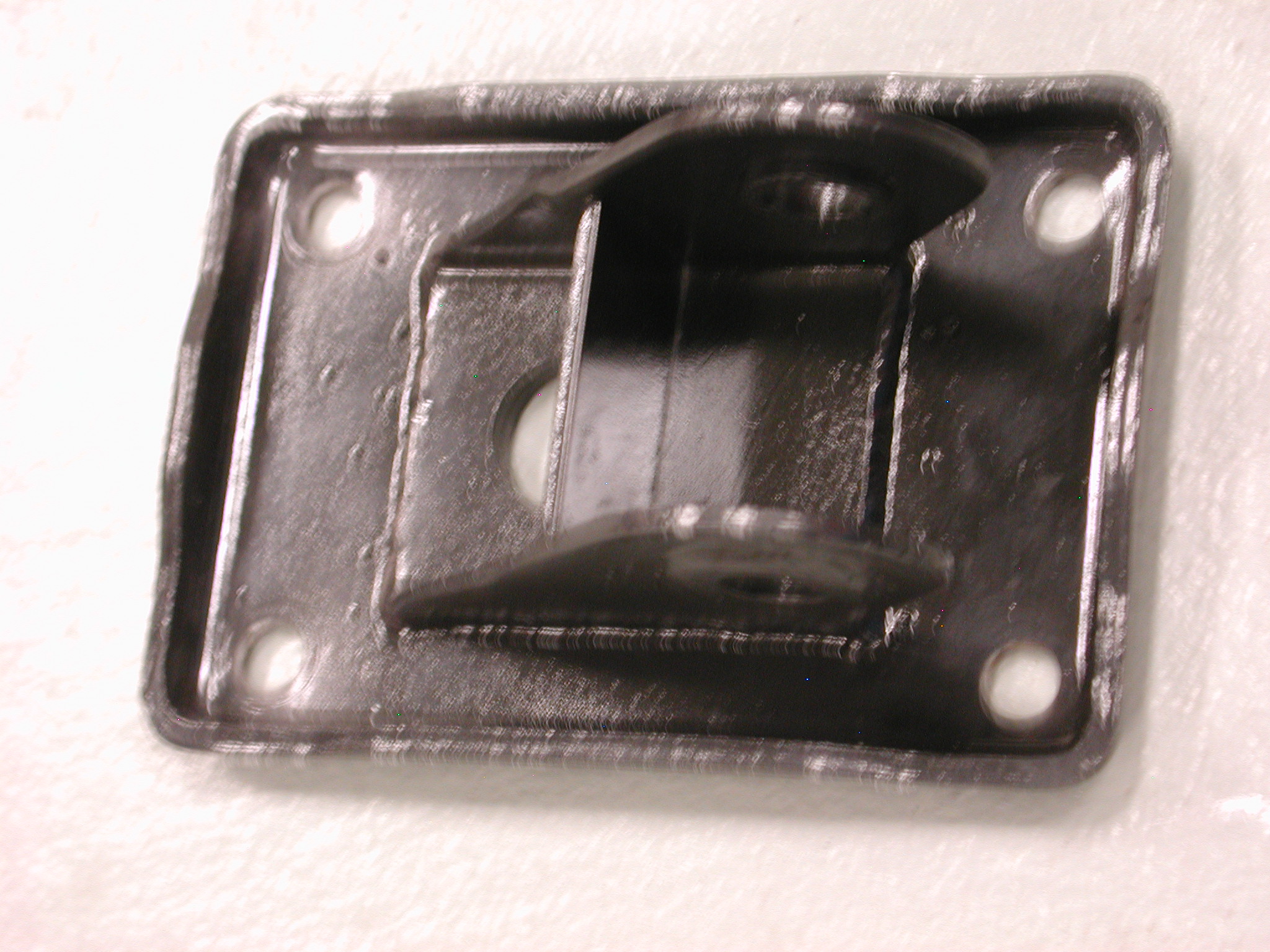
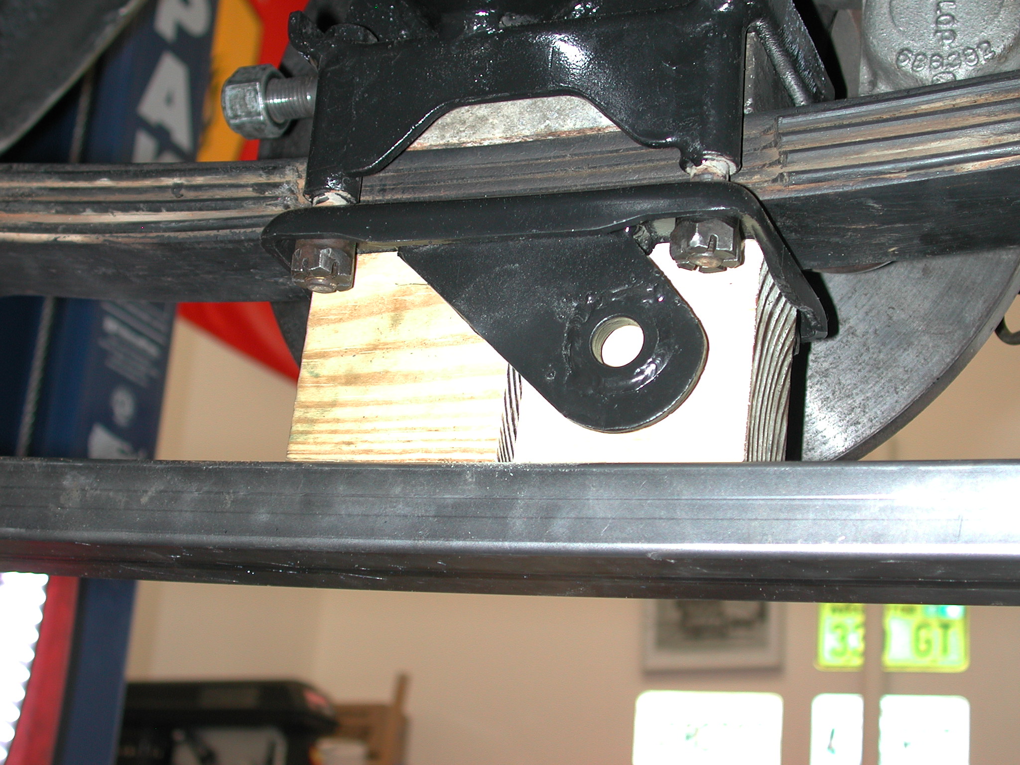
The shackles and springs are loosely bolted together and then that whole assembly is bolted onto the stud at one end and attached with a bolt at the other. Then the spring compressor is loosened and taller blocks of wood are inserted to keep the spring compressor out of the way while fitting the lower radius rod attachment plate (39). After a few taps of a hammer, the bolts aligned with the plate. It was one of these bolts that had sheared during removal. It turns out that this bolt was unique, 10x1.0mm, 105mm long. This is a very fine thread (10mm are usually 1.5mm pitch/coarse or 1.25mm pitch/fine). Luckily, one of Lowell's friends had rebuilt the rear suspension on his GTE a long time ago, but had a used bolt and some nuts. Note the recessed area that fits over the nut (27) holding the leaves of the spring together. I asked Lowell why he didn't just use to blocks positioned to each side of the plate to hold the spring out of the way. He said that he was more comfortable in having the tops of the blocks captured by the lip of the plate and thus couldn't get knocked out of position. There is lots of force involved with the leaf spring, so anything that makes the operation safer is good. Getting all of the holes, washers and bolts to line up is difficult. The spring assembly has a mind of its own until it is firmly attached on the differential. Lowell found that tapered drift pins, tapered bolts and pry bars were essential to get everything put together.
The coil over springs were cleaned and repainted black. Lowell noted the spring rate markings and reproduced them on the repainted coil springs. This is the white paint near the top.
Re-assembly is in the opposite order:
- Upper radius arm (not shown).
- Spring and shackle assembly (27 and 12) as a unit.
- Lower radius arm fitting (39).
- Lower radius arm (36).
- Coil-over spring and shock assembly (5 and 17) as a unit.
- Exhaust system.
Once the driver's side was done, Lowell went to work on the passenger's side. It is always good to keep one of a pair intact until completely done with the first. That way, any questions of re-assembly can be checked against the intact side. As Lowell was working on the passenger's side, he noticed that he had assembled the nylon washers on the front top shackle incorrectly.
After all of the problems getting the shackle off the stud on the driver's side, Lowell was ready to have to fight this side. He put on the puller and tightened it, but it kept slipping off. Finally, he realized that it was slipping off because the shackle was moving easily and the puller was just getting loose. Then the shackle came off just by pulling with his hand. This side had the same problem with the bushing (20) completely missing.
Everything was cleaned, repainted and new silent blocks and bushings fitted.
During re-assembly, Lowell forgot that the upper radius arm needs to go on before the forward end of spring and shackle assembly is installed as it gets in the way of mounting the upper radius arm. He was able to drop just the front end of the spring and shackle assembly to mount the radius arm.
When the passenger side was complete, Lowell went back and fixed the nylon washers on the driver's side. This required removing the shock assembly and lower radius rod. The blue arrow points to the special washer (10). The red arrow to the nylon washer (9). The green arrow points to the replacement silent block and washer for the lower shackle mounting bushing (20-22). You can click on the picture for an enlargement.
Once everything was back together with the shackle and radius arm bolts and nuts loose, the car was set down on the suspension and everything was tightened and torqued down. This locks the silent blocks in the middle of their rotation, so they are not overstressed when a full compression of the suspension (over a bump) occurs. All of the cotter keys were put in and yellow paint daubed to denote that the nuts were properly tightened.
In the 'While I Was There' category, Lowell also:
- Painted the axle housing.
- Painted a portion of the fuel tank.
- Fixed a tear in one of the muffler heat shields.
- Filled some holes in those heat shields with JB weld.
- Welded up or patched holes in the mufflers
- Cleaned and painted various parts of the exhaust system.
-
Replaced the collectors and re-aligned the exhaust system.
So a project that was started in February was completed in May.