Alternator
On the way to Whistler, BC, I noticed that the ammeter was showing about -20 amps discharge. Fiddling with the fuse didn't resolve the problem. We stopped in Squamish at an auto/tire center. I figured that I could always buy what I needed if I could figure out what the problem was.
I thought that I might have not got the alternator connections put back right since I had it out trying to install an auxiliary radiator fan. But a double check of those and the ones at the voltage regulator didn't turn up any problems. So we motored on, only having about 45 minutes to go at that point. I knew that the battery would provide enough power for the ignition and once we got moving, the radiator fans would stop as the air flow through the radiator would keep it cool.
We stopped on the way into Whistler to buy a volt-ohm meter so I could do some more electrical testing. I also borrowed a battery charger from a friend. I figured the worse case would be to start home with a fully charged battery, buy a spare and between the two, we should get home as it's only a 4 hour drive.
More testing on the alternator revealed that the field (rotor) circuit was open. I called up Lowell Brown who has an identical car and his measured 6.8 ohms. At least I now knew what the problem was. I didn't have much in the way of tools but my friend is a millwright by trade and does have lots of them.
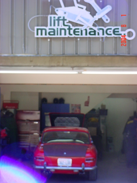
We drove the car to his work place and proceeded to take out the alternator. The 'lift' in lift maintenance isn't for a auto lift, but ski lifts. BTW, you can see my primered trunk, to be painted as another 'to do' before leaving for Monterey.
Once out, we started to take it apart. The first problem we saw was that the three screws holding the bearing backing plate to the case were loose. The only reason they hadn't fallen out was that the pulley was in the way. However, the rivets on the pulley had hit the screws and bent all of them. We got the pulley and the end of the case by the pulley off, but got stymied. The rotor wouldn't come loose of the bearing at the far end. Further there wasn't really any way to pull it off. Tapping with a pin punch through a slot at the far end onto the rotor didn't move it either. Finally we unscrewed the three nuts on the diode blocks. That didn't free the rotor, but it did allow us to remove the stator (fixed windings) and the permanent magnet that comprise the center section of the alternator. This exposed most of the rotor.
Sticking out from between the metal poles was two wires with worn off ends. Aha, maybe these are supposed to be connected together? A resistance test revealed that one wire connected to ground and the other to the field terminal. The wrap holding the wire coil together had broken on this side. This allowed the end of the wire coil (where it went back to the center to connect with the slip ring) to fly out through the gap in the rotor poles. Then the wire rubbed on the metal frame of the stator until it wore through. There was just enough wire to strip off the varnish and solder it. Then we wrapped the whole outside of the coil with some special dielectric tape designed for this. Here's a picture of the rotor with completed repair circled.
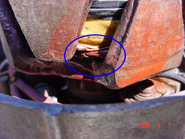
The red is from the Glyptal spray used to insulate the connection. From there it should have been easy. However, that was not to be. The stator windings terminate in three studs that go through the diode blocks where they are fastened. These have to be aligned just right at they have hex fittings that need to fit in recessed in the blocks.
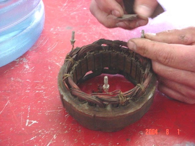
You can see that the studs are easily moved out of place as they are just soldered on the wires. After some tries and adjustments, we got each of the studs through the holes enough to get the nuts on. But success was fleeting. As I was tightening the nuts, one of the studs sheared off. It turns out that I wasn't the first one to do that on this stud. A careful inspection revealed a short piece of copper wire sticking out from one side that fit into the hole in the other. So it was back to soldering to put the stud back together. We had to do this three times before we got a good enough solder bond to allow the nut to be tightened just a little over finger tight. Some Loctite was used on the nuts to prevent them from coming loose.
After the alternator was re-installed, I started the car and was very pleased to see the ammeter kick over to a +35 amp charge.
The fix worked fine for years until I noticed that the ammeter was charging at -10 amps. The fuse was blown. Replacing the fuse and a quick test showed everything to be fine, but a longer drive would blow the fuse again. Spent quite a bit of time working on the voltage regulator before deciding that the alternator must have a problem again so I removed it and took it to an auto electric shop.
The alternator was showing an open circuit on the field to ground when it was tested at the auto electric shop. Once it was apart, the problem was obvious, the same wire that had worn through several years ago had come loose again and was making intermittent contact. It turned out that the wires wound on the rotor weren't tight to the center, which is probably why the wire came loose again. In addition, once that wire was fixed, there was another break further inside the winding, so the rotor has to be sent out to be rewound. One of the four brushes was stuck in the holder and needs to be fixed. So now I wait for a couple of weeks for the rotor to come back.
I got a call from the shop and finally everything was back and finished. They also replaced the bad stud that had come apart before, along with replacing a bearing and everything else that looked suspicious. So the alternator should be good for my life-time now. They also bead blasted the case while it was apart and used a marine sealant on the exposed portion of the field coil.
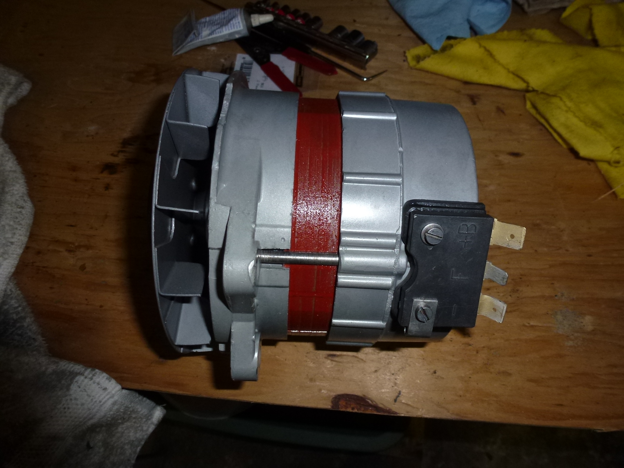
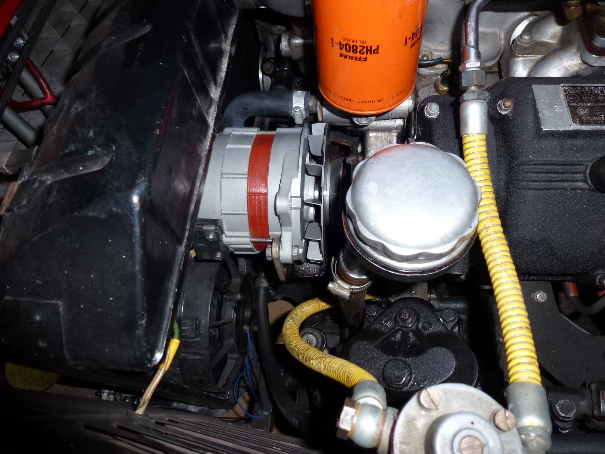
Installation was just the reverse. Slip the alternator into place, using the front bolt slid in just enough to hold it in place. Then align and tighten the rear bolt. Put the Nylok nut on the front bolt and tighten both until there is resistance moving the alternator. Then move the arm back in place, adding the bolt, lock washer and nut. Using a lever, swing the alternator tight against the belt and tighten the adjustment bolt. Then go back and tighten the other bolts. Finally, replace the crankcase vent and cap.
Of course, the final test is starting the car and seeing the ammeter move over to +35 amps.
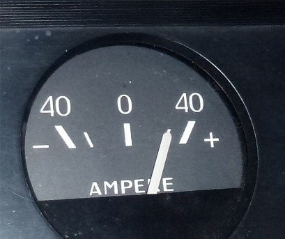
The auto electric shop said that the alternator put out 55 amps with his test voltage regulator, even though it is only rated at 40 amps.