Accelerator Linkage
In the process of working on the carbs, I found that I was missing most of the accelerator linkage.
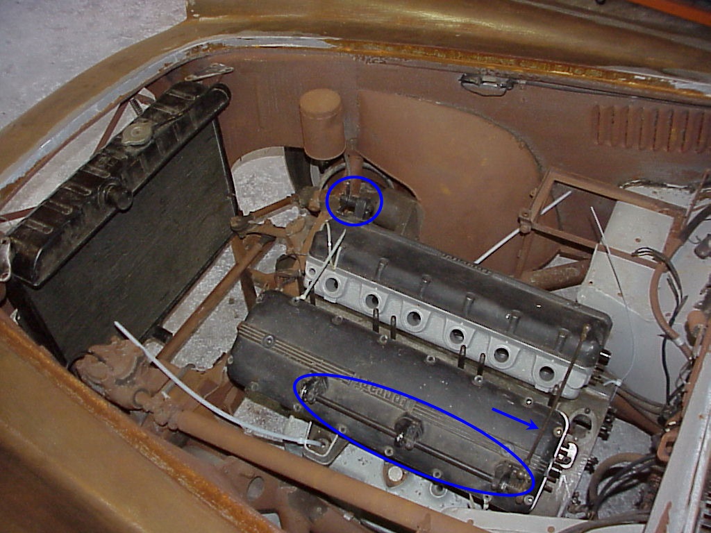
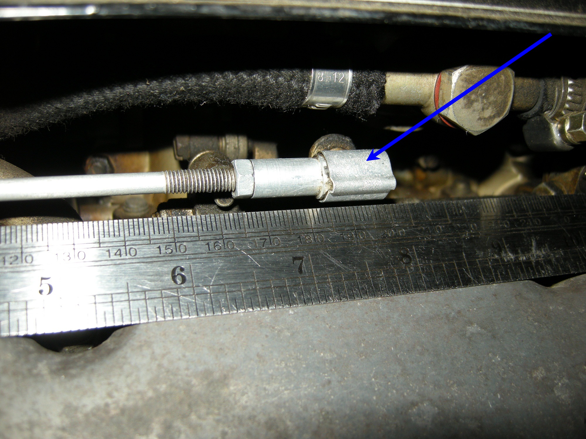
One of the linkages connecting the carburetors to the accelerator shaft weren't there. The linkages were also missing all of the lock nuts and spring clips that hold the end balls into the sockets. As I was thinking about the missing linkage, I realized that I couldn't remember seeing the accelerator shaft and linkages that mount to the valve covers. I went looking for those and came up short. Here's those missing parts pointed out in a picture of the 1765 engine as I was getting ready to sell it.
An email to Shaughnessy asking about the accelerator linkages got a terse reply of 'No problem', so presumably I'll get everything I need there at some point.
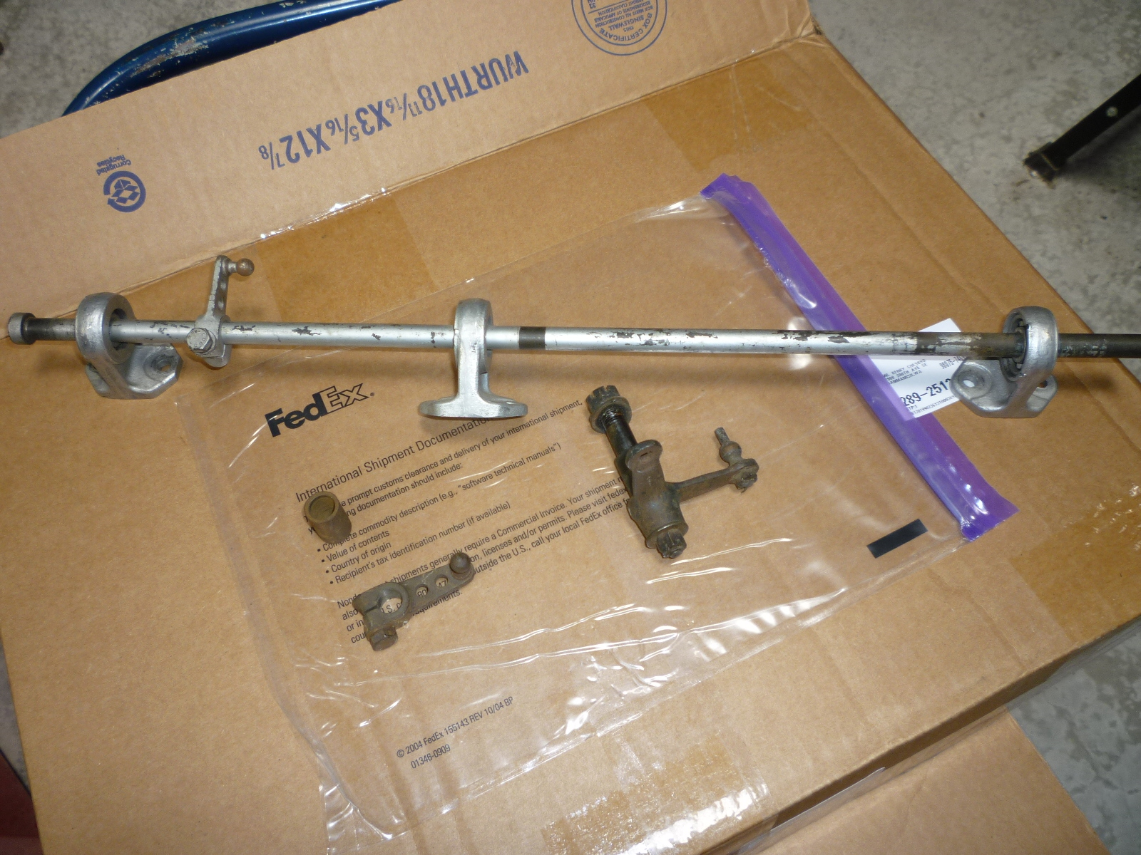
A couple of packages came from Tom. So I now have the stands, bearings, two arms, rocker assembly for the other valve cover. Just need one arm for a carb, arm and linkage to fit with the rocker assembly and I'll be in business. I also need one of the adjustable linkages to go to a carb and all six of the spring clips that hold the linkages onto the balls. Of course, everything needs to be stripped and finished, wrinkle paint for the stands, cad for the socket ends and black oxide for the rest.
I ordered a couple of sockets and balls for the accelerator linkage from a Mercedes parts place as they look like the Ferrari ones. They will have to be modified once I get them as Ferrari used a pin on the ball going through a slot in the socket with a washer and cotter pin to prevent the two parts from coming apart. The original balls are 9mm in diameter while these replacements are 8mm. So they aren't quite right, but close enough for now.
I was also missing one of the three linkages to the carbs along with all of the spring clips that hold them in place. The spring clips are available under a Dino 246 part number and I had a friend with a Dino email me some close-up pictures. In addition, I went over to Jon Shirley's place and took a bunch of pictures of his LWB California accelerator linkage as that car is just a few serial numbers later the the coupe.
 Dino Linkage |
 250 LWB Linkage |
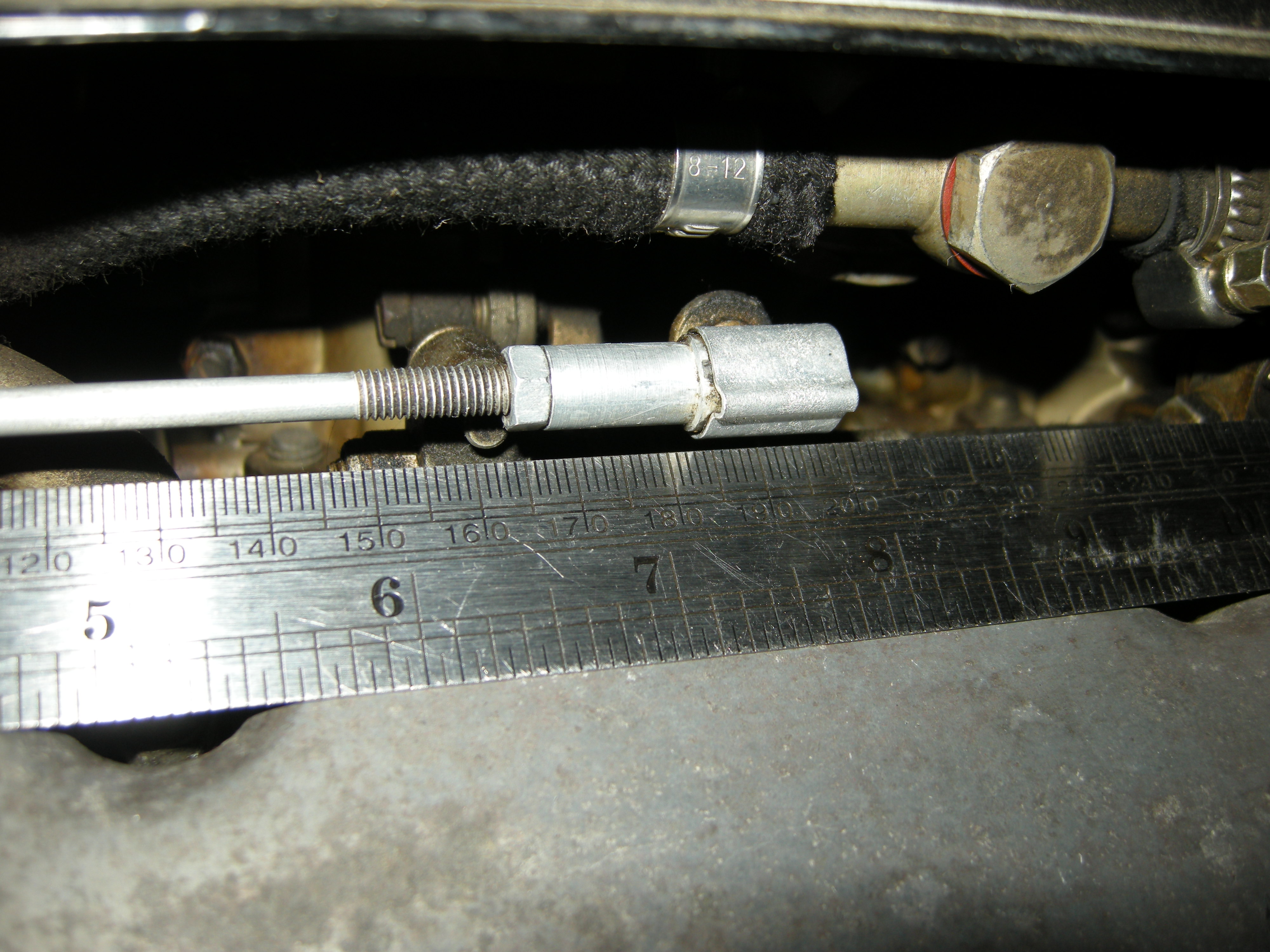
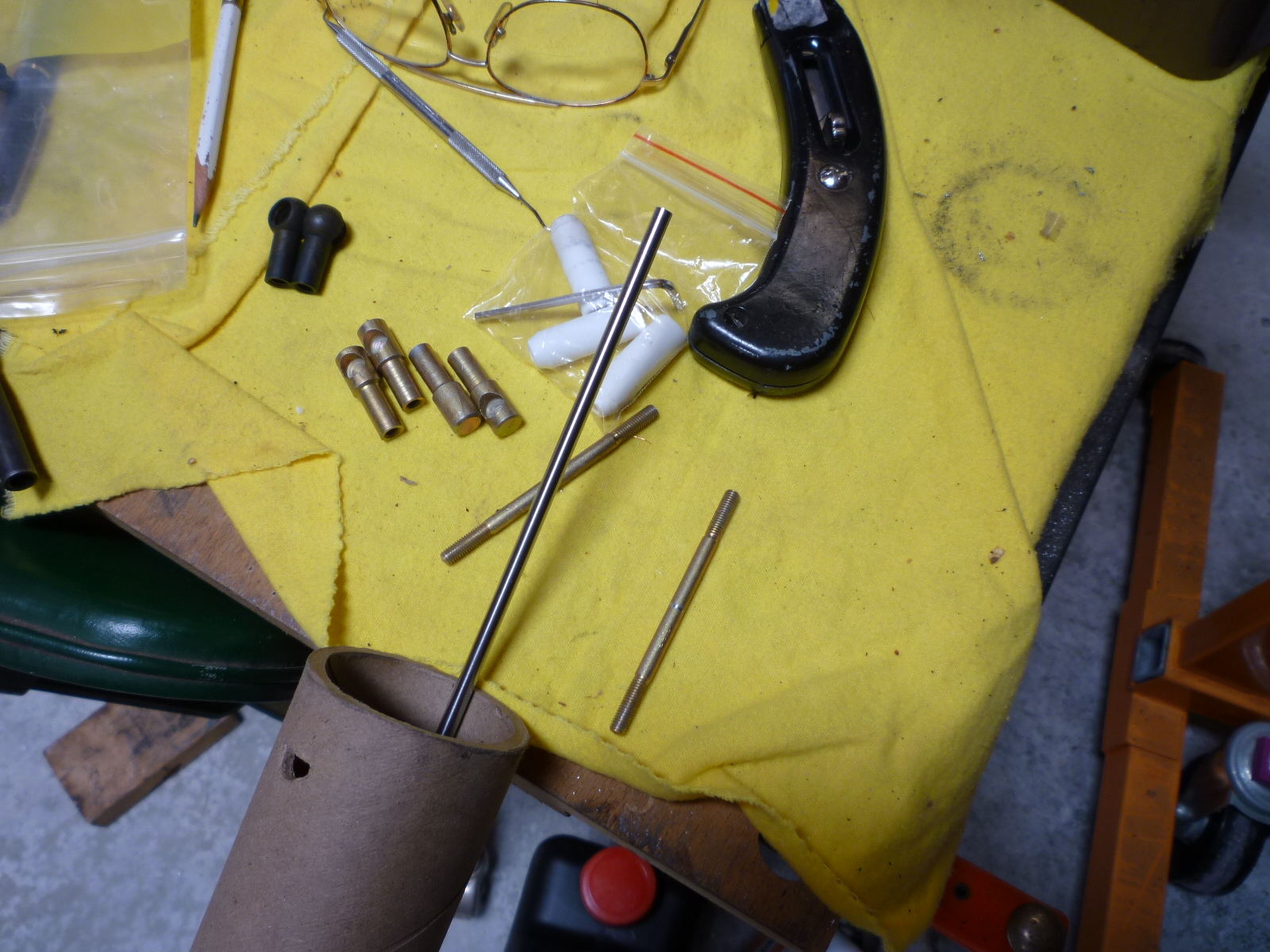
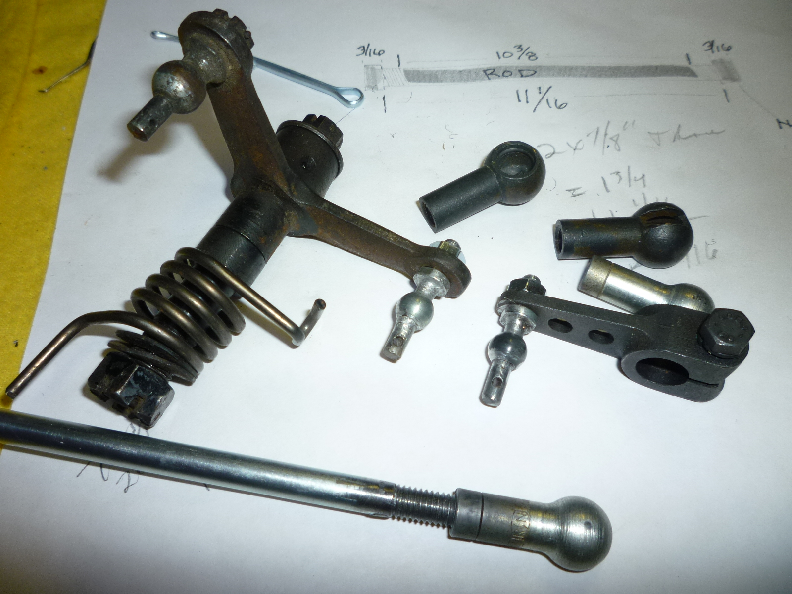
For the missing carb linkage, I needed two ends that McCann had. The six Dino clips are coming from Ricambi. For the rod, I got some 5mm steel stock from McMaster-Carr. I had to buy a 6' length to get in in a mild steel. I cut off the proper length and threaded each end. Luckily, Ferrari used right hand threads on both ends. Some cars have LH thread on one end and RH thread on the other, thus allowing you to adjust the length simply by loosening the lock nuts and rotating the shaft. On a Ferrari, you have remove the clip and pull the socket off the ball and then rotate the end to make an adjustment. Here you can see the raw stock and the newly made part.
Most of the accelerator linkage is finished in black oxide. The exceptions are the socket ends which are cadmium plated on 250 models (nickel for later cars). So once I get all of the parts, I'll have to get them properly finished.
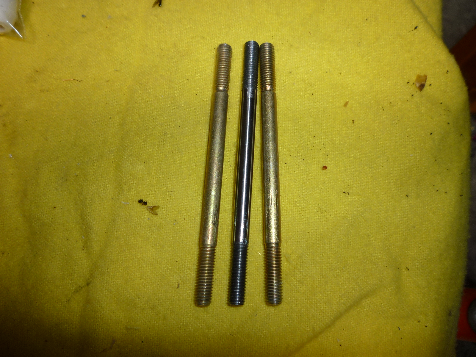
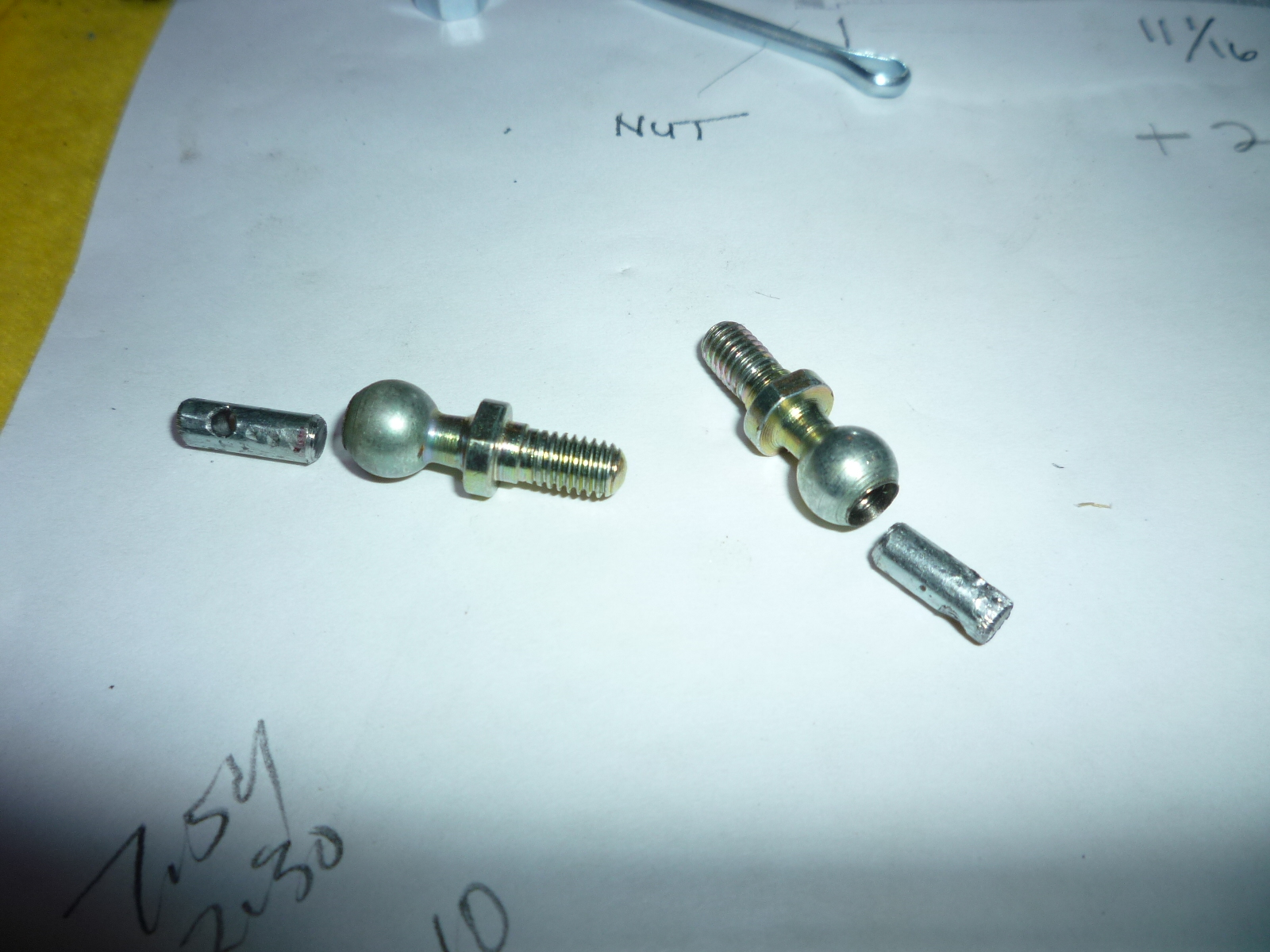
The order from the MB parts place came with the sockets and balls I needed for the linkage between the two valve covers. For the 6mm rod in between, I bought a 3' piece of 1/4" rod from Lowe's. Just .014" too large, I ground the ends before threading them. The sockets were threaded for 5mm, so I had to drill them out and re-thread them. They were quite hard and I ruined a couple of drill bits. It was also very difficult to get the tap to start threading. Finally, I chucked a 1/4" socket adaptor in a battery drill, attached a tap adaptor and then inserted the tap. Now, I could really lean on the tap while letting the drill slowly turn the tap. My neighbor with the industrial drill press mentioned that a better was is to put a pin in the drill press that presses down on a tap handle. Then you use the drill press for the pressure and turn the tap handle to get the threads started. Too bad I didn't talk to him first. Here you can see the new rod with the new socket and ball, along side originals.

The ball needed to have the pin for the cotter pin added. In order to do this, I had to locate some 4mm stock. I went around the house, measuring nails, peg board hooks, screw hooks, etc. Finally I found a gate latch that was exactly the right size. After straightening it, holes were drilled for the cotter pins. Then two lengths were cut and matching holes drilled in the ends of the balls.
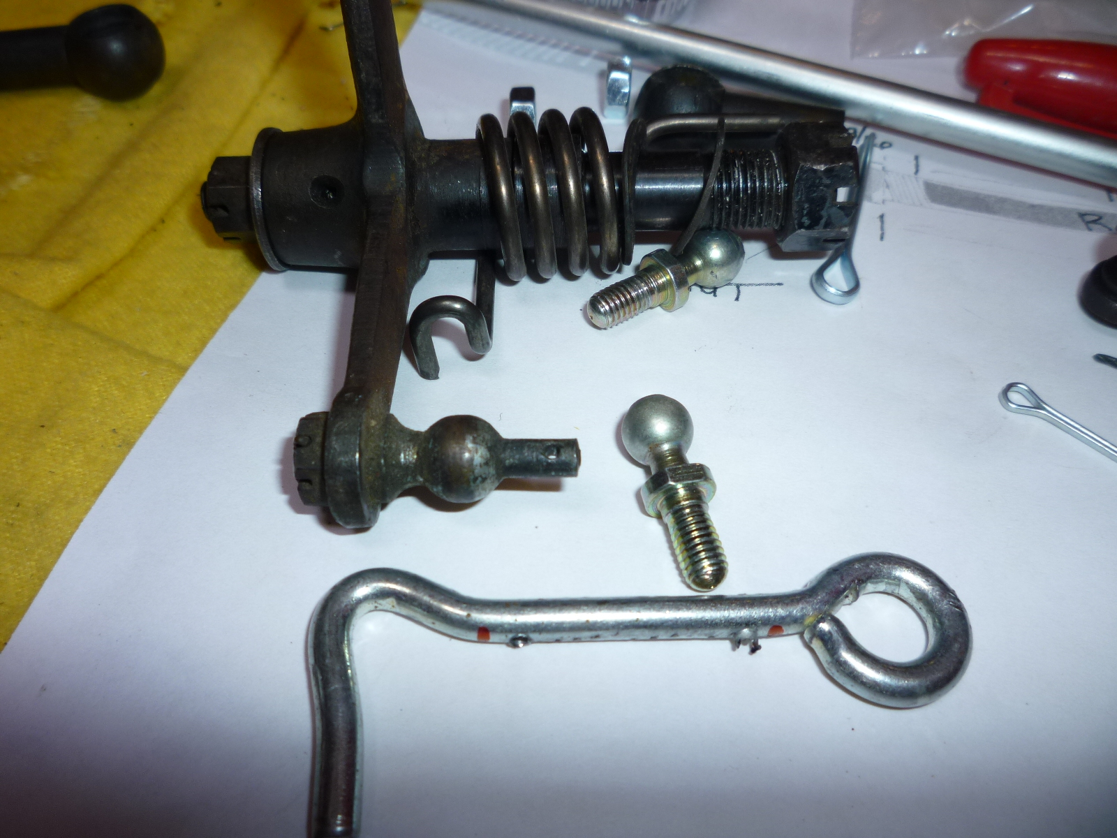
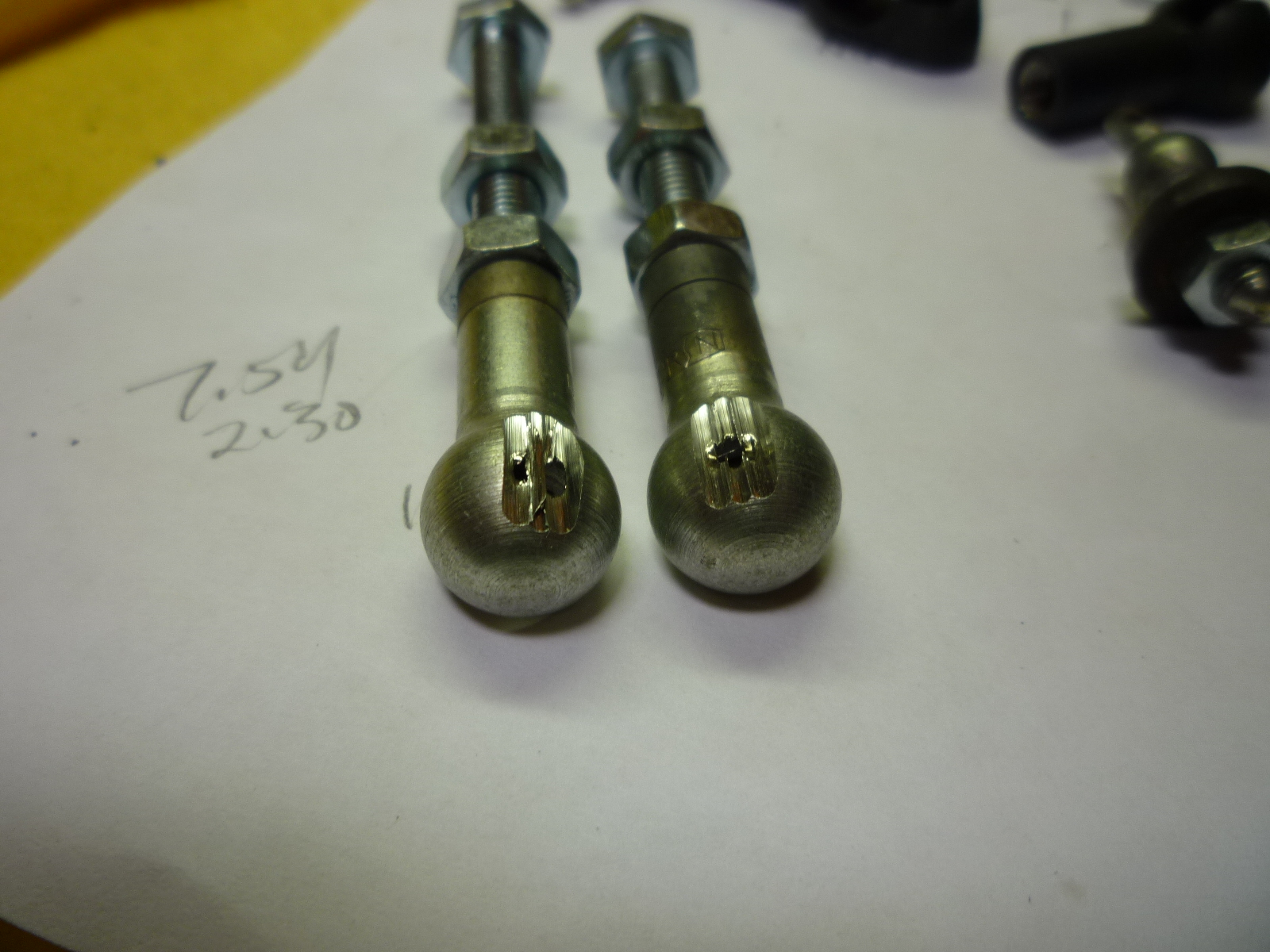
Then I soldered the pins into the balls. The last item was to modify the lever arm mounted on the throttle shaft. I couldn't find an arm with just a hole for the modified ball, so I ended up using one with a peened on ball removing it by grinding off the peened over end and driving out the ball. Then the modified ball was attached with a nut. I do have to get some 5mm castellated nuts to properly attach these two balls and drill holes in the threads for the cotter pins. The original balls and sockets are actually 9mm, but I had to use 8mm as that was all I could find. However, it will be easy to replace these if I do find the proper size in the future. Here's everything ready to bolt together except for the slots in the back of the balls. Tomorrow's project.
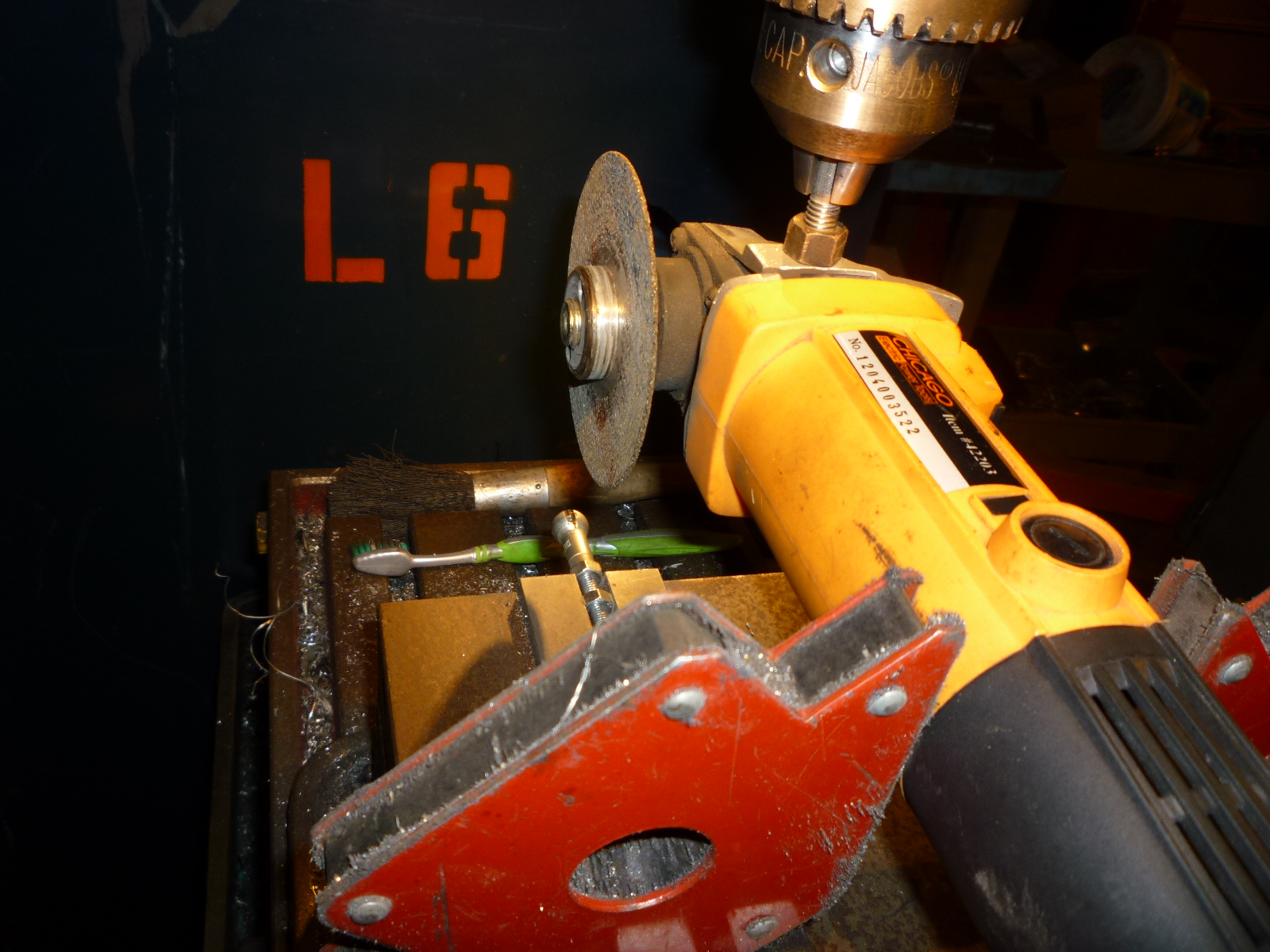
After thinking overnight about how to cut the slots in the sockets without just free-handing it a cut-off wheel, I came up with a Rube Goldberg solution. First I found a bolt and nut the right size to fit the handle screw on the cut-off tool. I cut off the head of the bolt and now had a shaft that would screw onto the machine. This could be put in the chuck of my neighbor's industrial drill press. The drill press would allow the cut-off wheel to be lowered onto the socket.
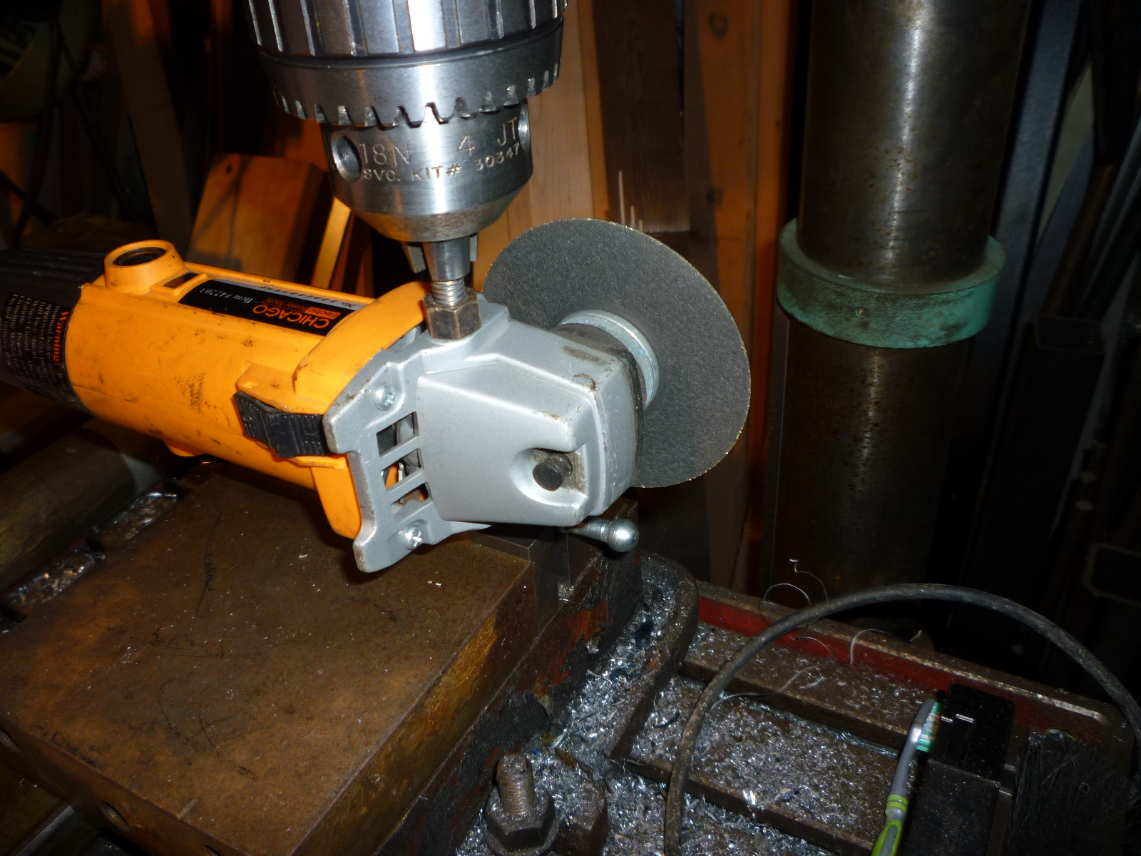
I screwed a bolt and two nuts onto the socket. One nut was used as a lock nut while the other and the bolt head was used to hold everything in the machinist's vise. A couple of magnetic right angle clamps held the cut-off tool parallel with the socket and bolts. Once everything was in place, it was just a matter of adjusting the cut-off wheel using the vise so it would cut slots in the right place. Three cuts made the slot wide enough.
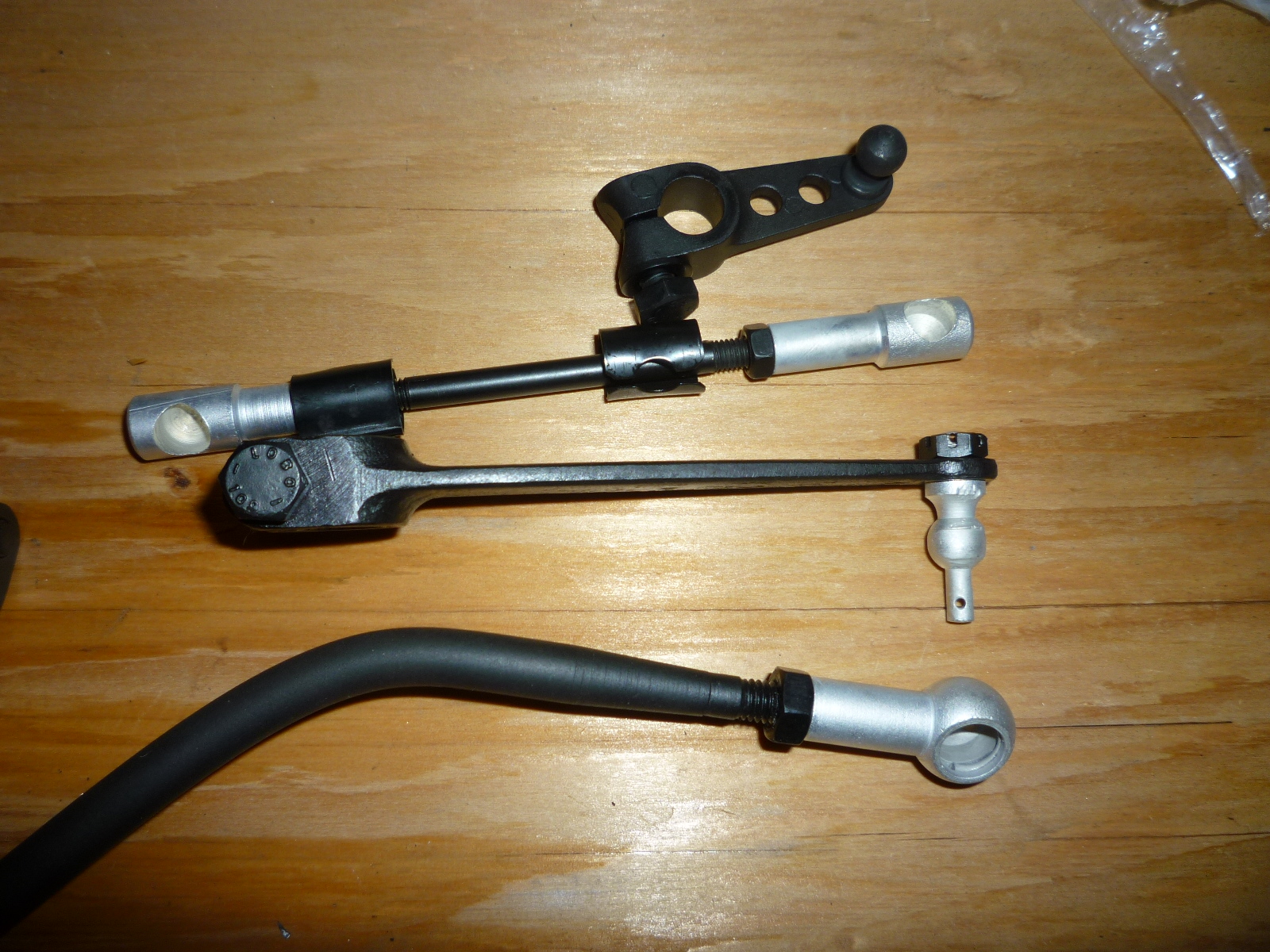
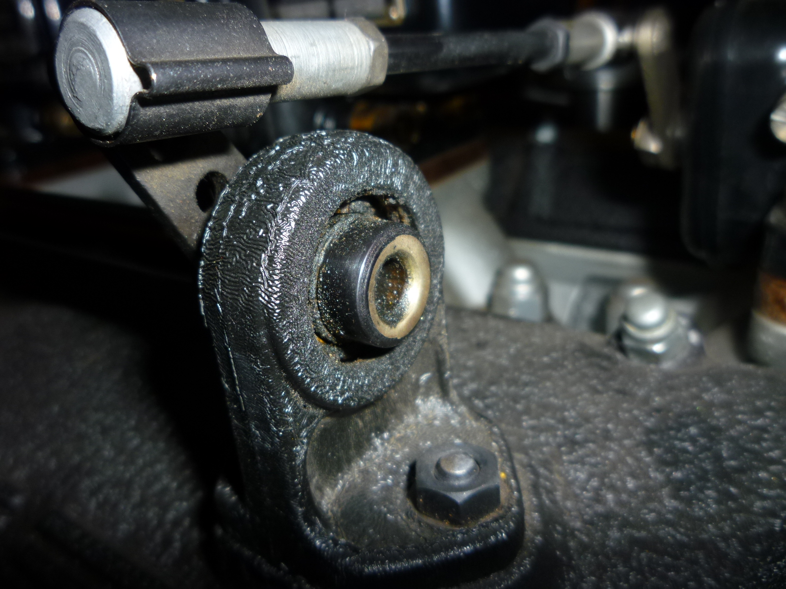
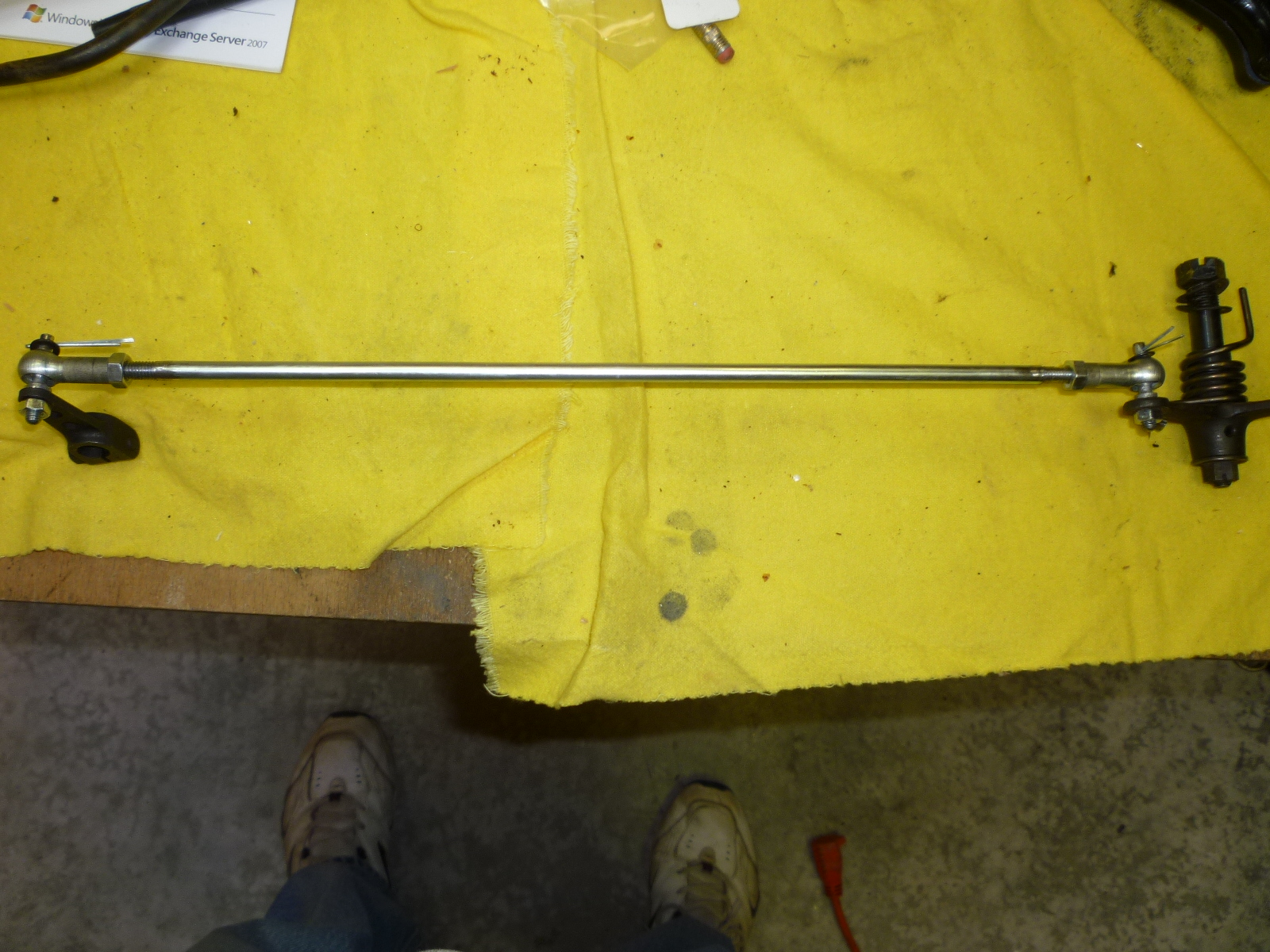
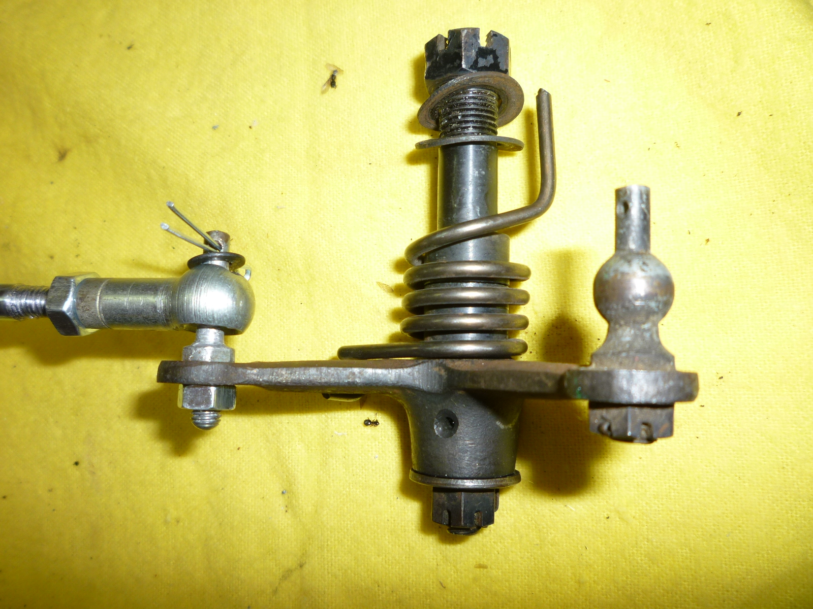
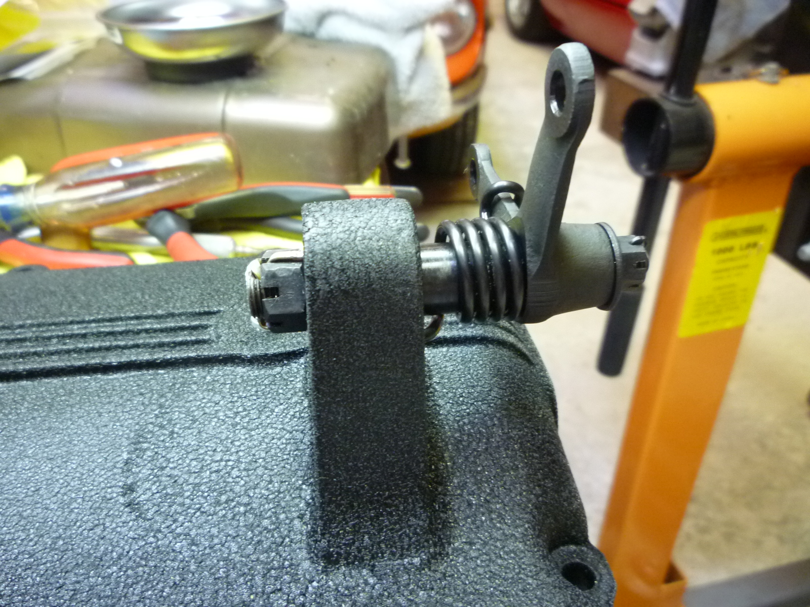
After that, I used the Dremel with a little cut-off wheel to smooth the cuts, along with some file work to clean up any burrs. Here is the completed accelerator rod with the ends that go on each valve cover along with a close-up of the left valve cover end. This end has one ball attached to a rod coming up from the accelerator pedal. As the accelerator pedal is depressed, the rod goes down, thus pulling the other rod and lever, causing the throttle shaft to rotate and the linkage to the carburetors to open the throttle plates.
Now I'm just waiting for the spring clips that fit over the sockets on the carburetor linkages. Then everything will get finished with nothing more to do until the carbs come back from Pierce Manifolds.
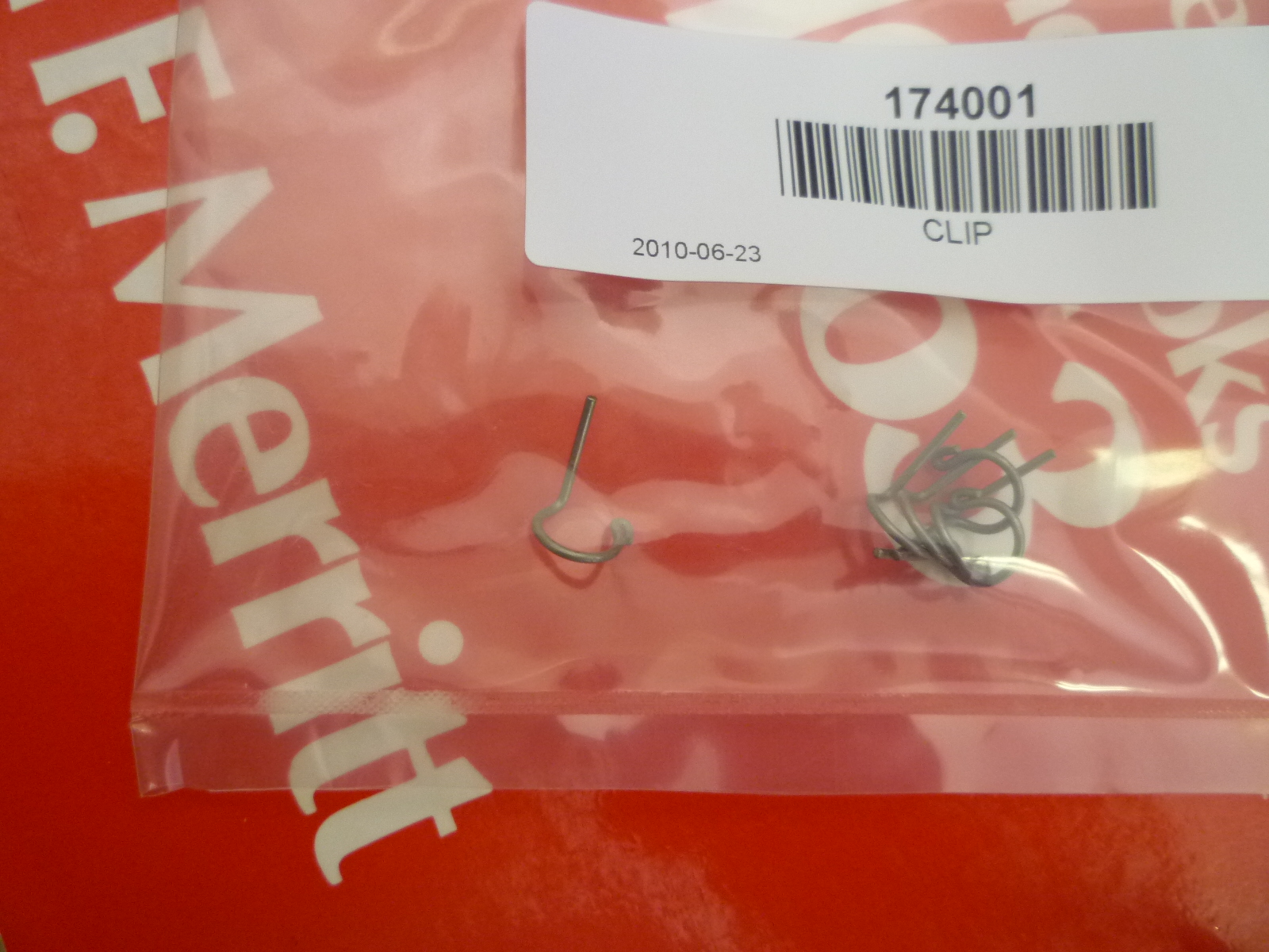
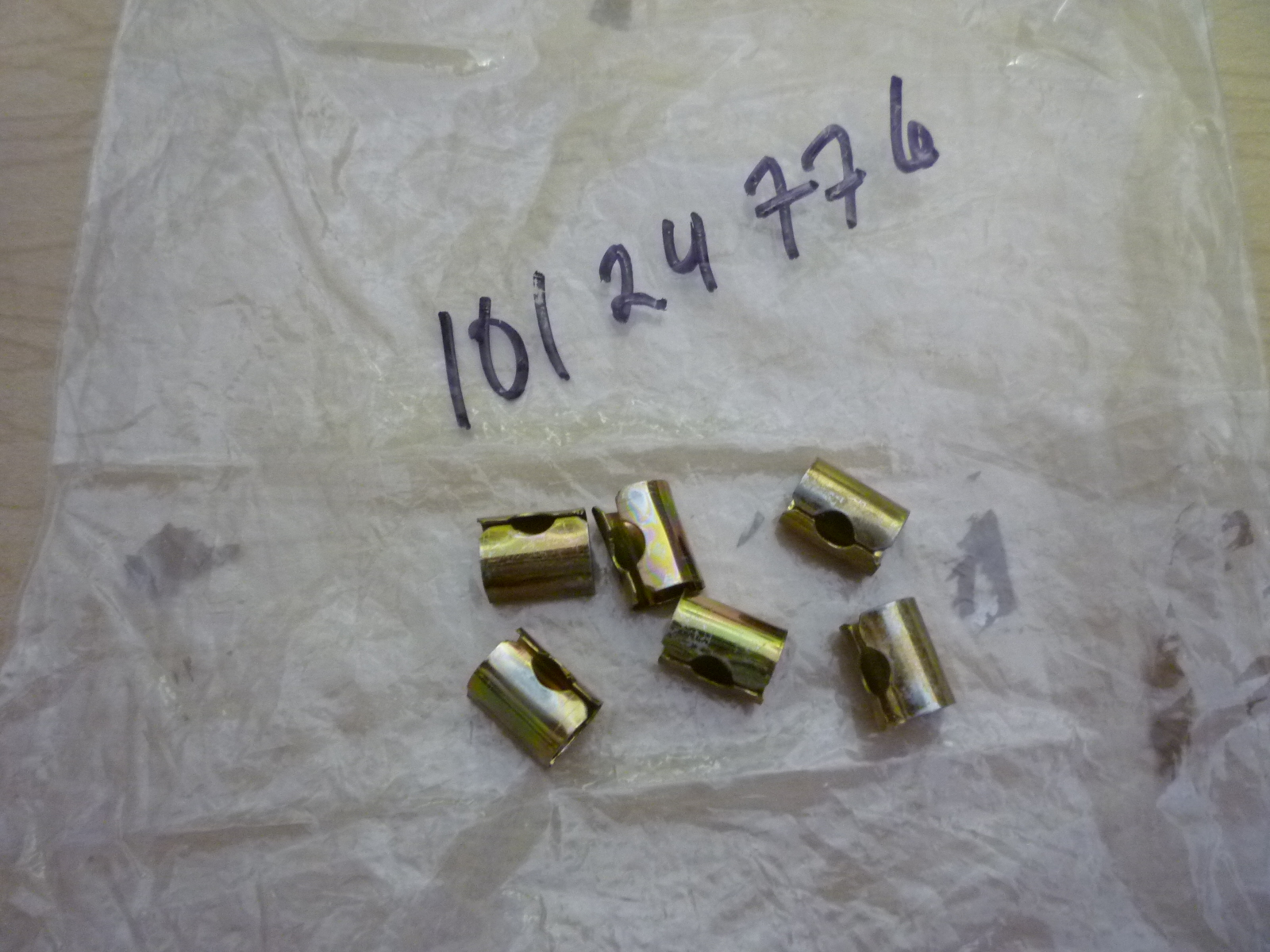
I'm also missing the spring clips that hold the carburetor linkage balls in the sockets. These are 94321, NLA. However, the 246 Dino uses similar parts, #10124776, supposedly superseded by 174001. I ordered them from Ricambi, but when they came, they look nothing like the Dino clip. In fact, I don't see how the 174001 clip would even work to hold the ball in.
Well, Dennis McCann still had some of the 10124776 NOS parts in stock, so I got six from him. Now I have all of the parts for the throttle and carburetor linkages, so I'll drop them off for black oxide processing. At the same time, I'll also drop off the parts that need cadmium plating such as the ball and sockets.
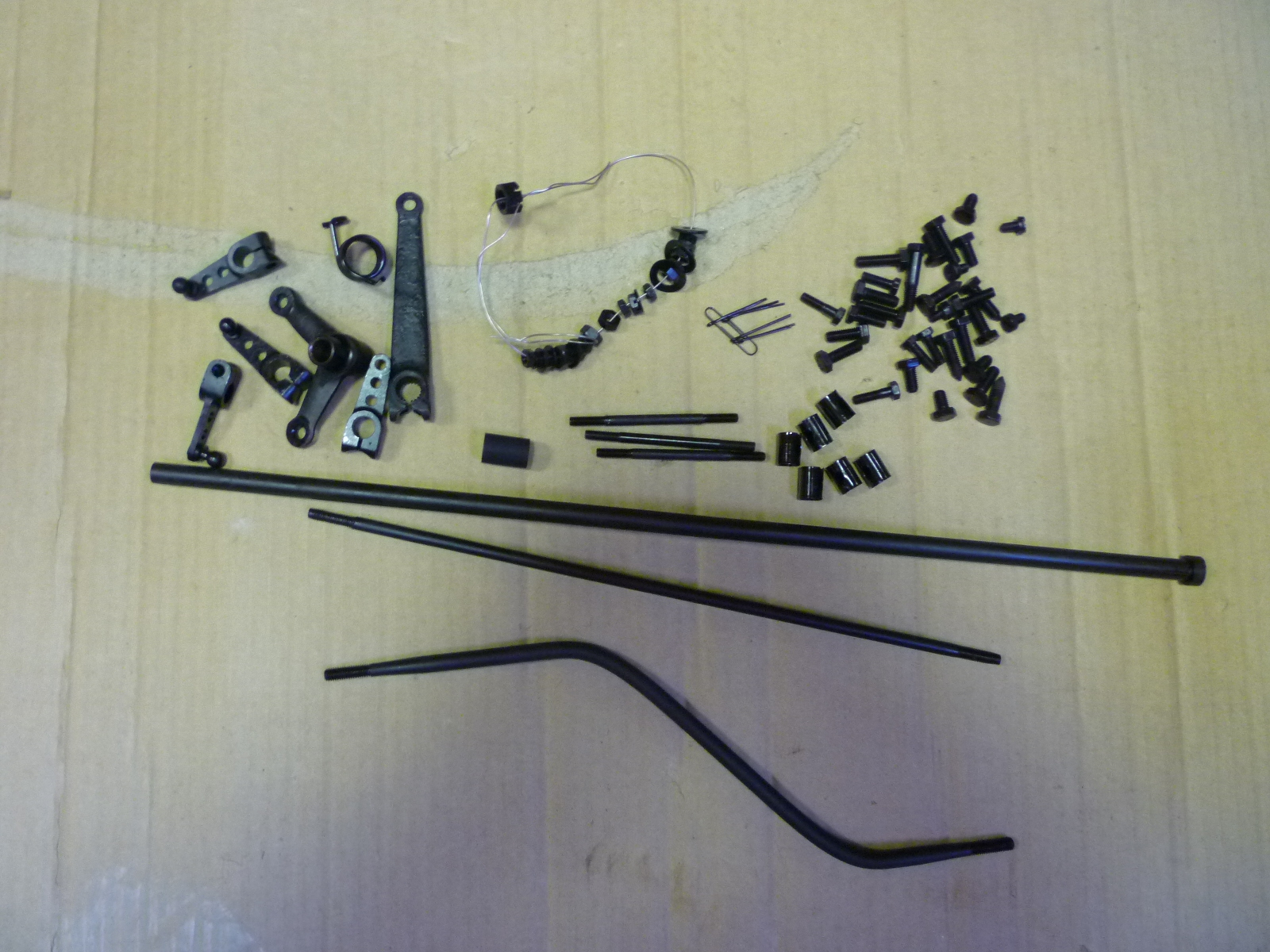
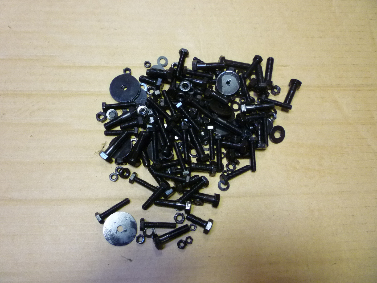
I got the parts back from the black oxide place. I had about 70 parts for the linkages and some bolts for the trunk. Since there is a minimum order, I bagged up about 2 1/2 pounds of various bolts, nuts and washers and got them done at the same time.
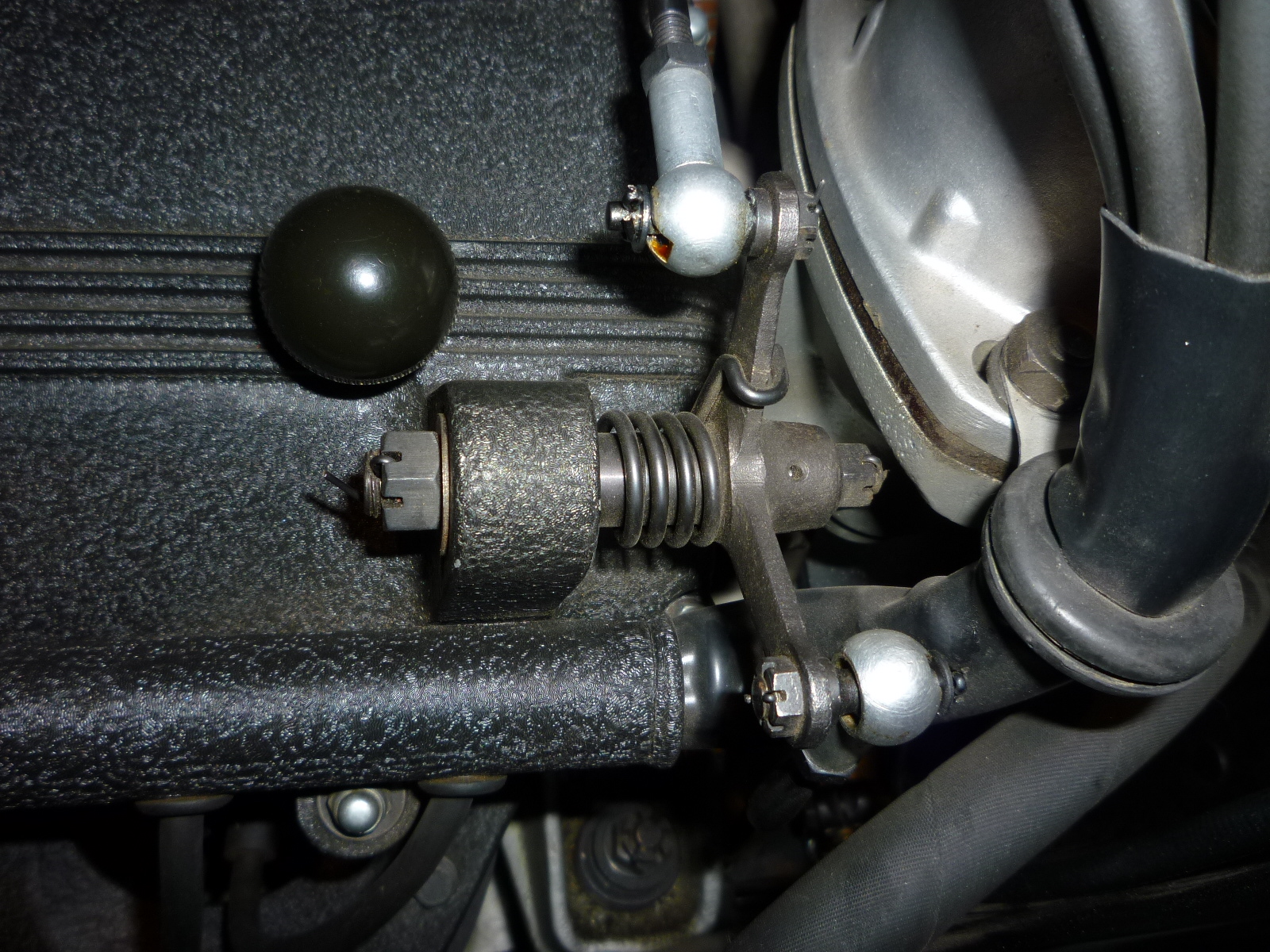
Then I started the re-assembly. First I put together the rocking linkage on the LH valve cover. The left picture is on a LWB Cal spyder while the right one is on my valve cover.
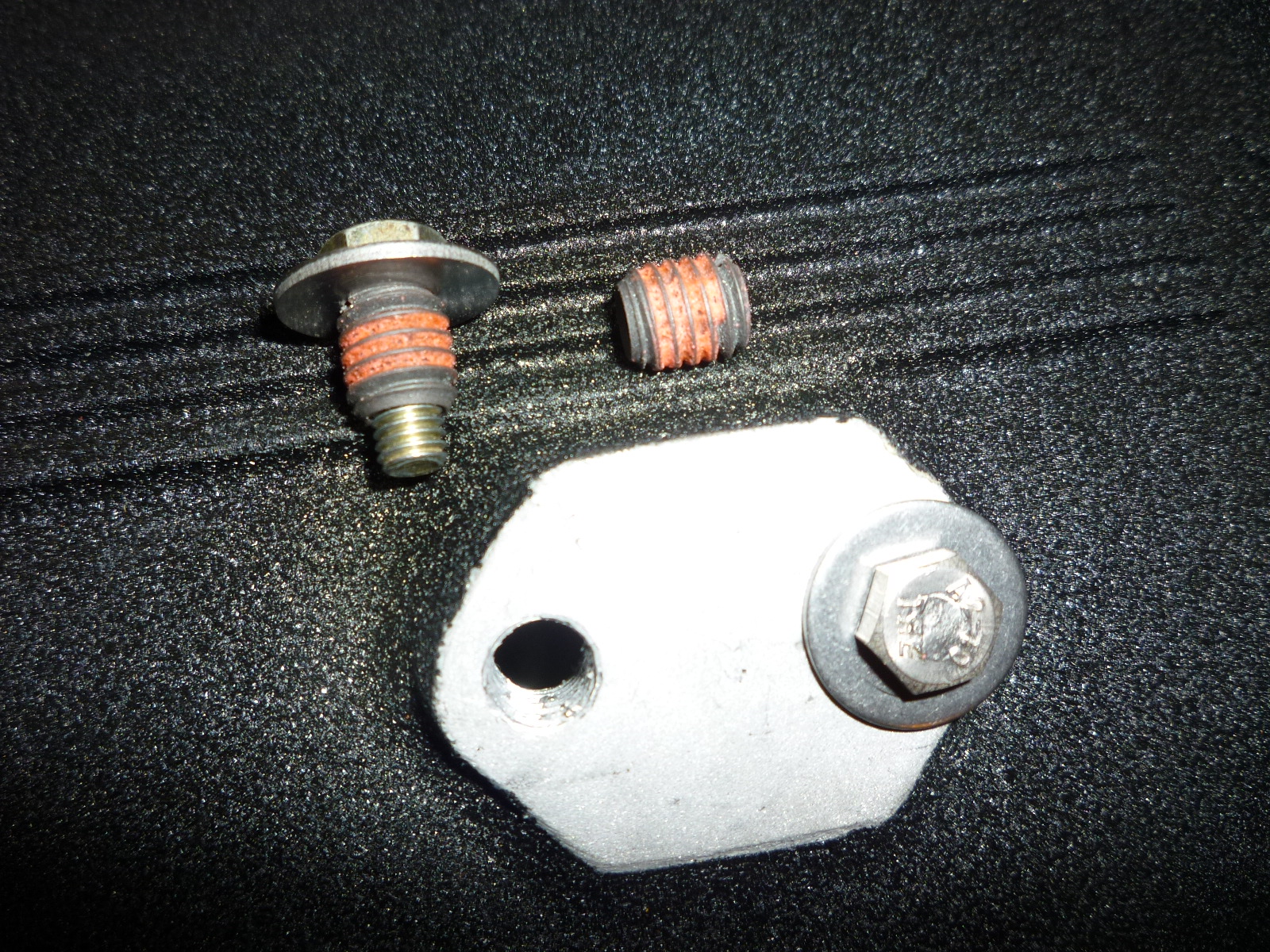
Then I started on the RH valve cover. I got out the supports for the throttle rod and quickly discovered that the studs were too large for the 6mm holes in the supports. After looking at the inside plug parts manual, I decided that they should be 6mm and someone had put in oversize studs, probably after having stripped the 6mm studs out of the valve covers. I originally thought that the studs were 8mm, but they turned out to be 5/16" fine thread. HeliCoils won't work since the tapped hole is already too big for a 6mm HeliCoil. The other choice is a product made by EZ-Lok. This is an insert with a metric inside thread and either a metric or US thread on the outside. The major difference between it and a HeliCoil is that it does not take a special tap for installation and the outside is larger. Specifically, I need the larger outside. I've used these before to repair a stripped welded on nut on the seats in the 330. I took out the 5/16" studs and put in the missing 8mm ones for the plastic balls that are on the valve covers.
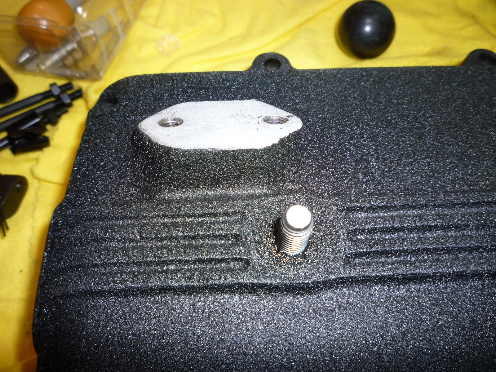
So this project will have to wait until I can get the inserts ordered.
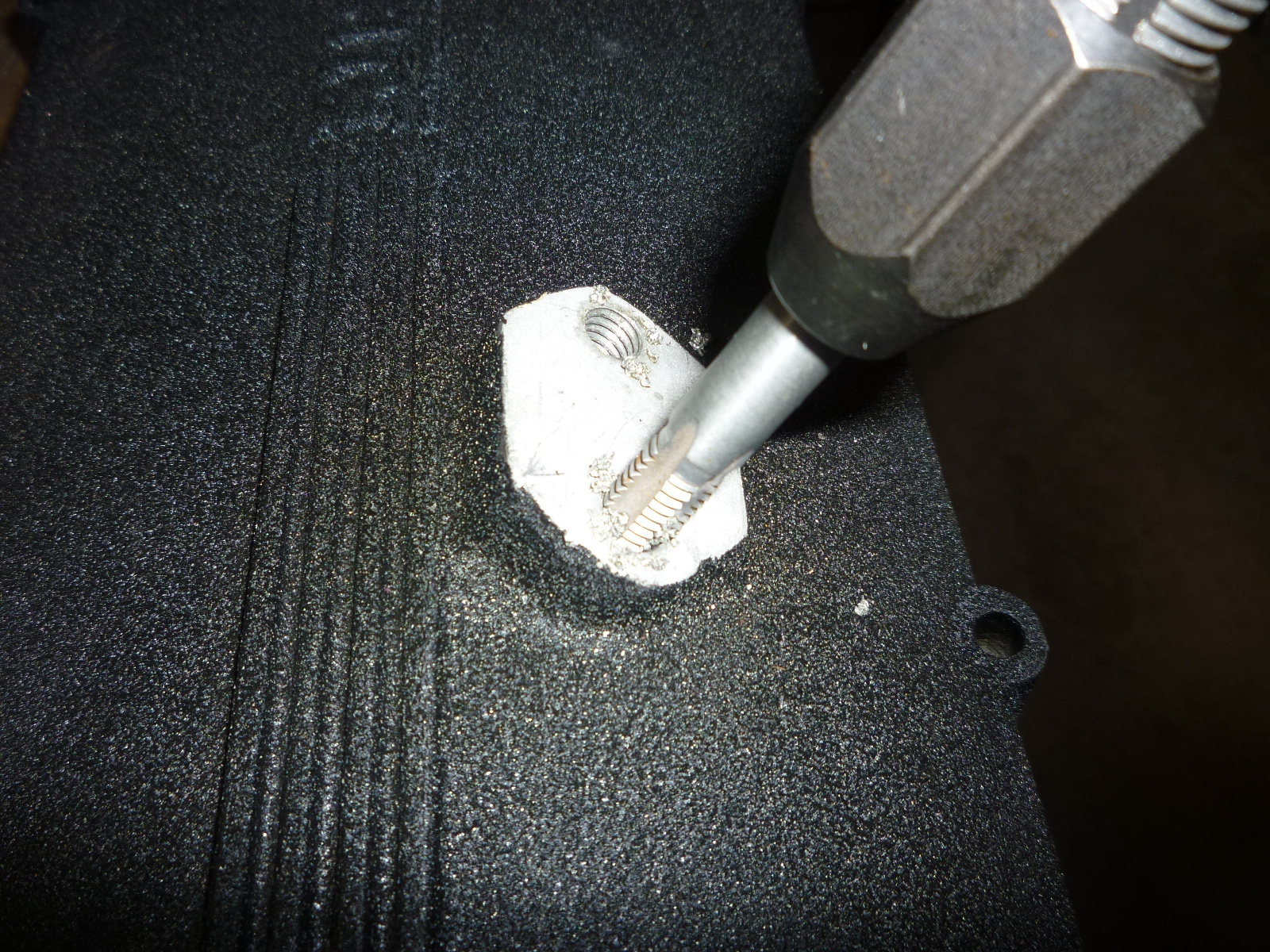
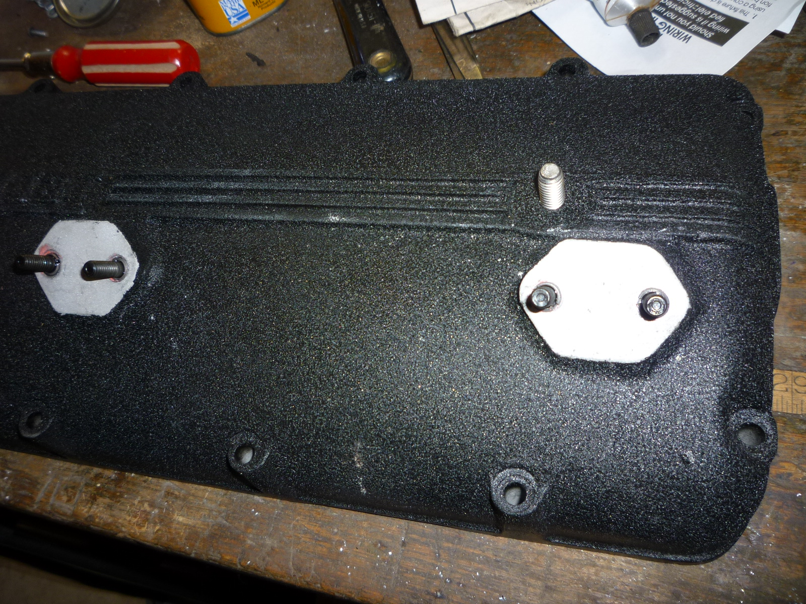
The inserts came, so I drilled and tapped each hole for the 3/8"x16 thread needed for the inserts. The inserts are installed by just screwing them onto a bolt and then using the bolt to install the insert into the tapped hole. The red on the insert is glue in little capsules that break on pressure, thus gluing the insert in place. The glue sets within a few minutes, so I was able to install the studs right away.
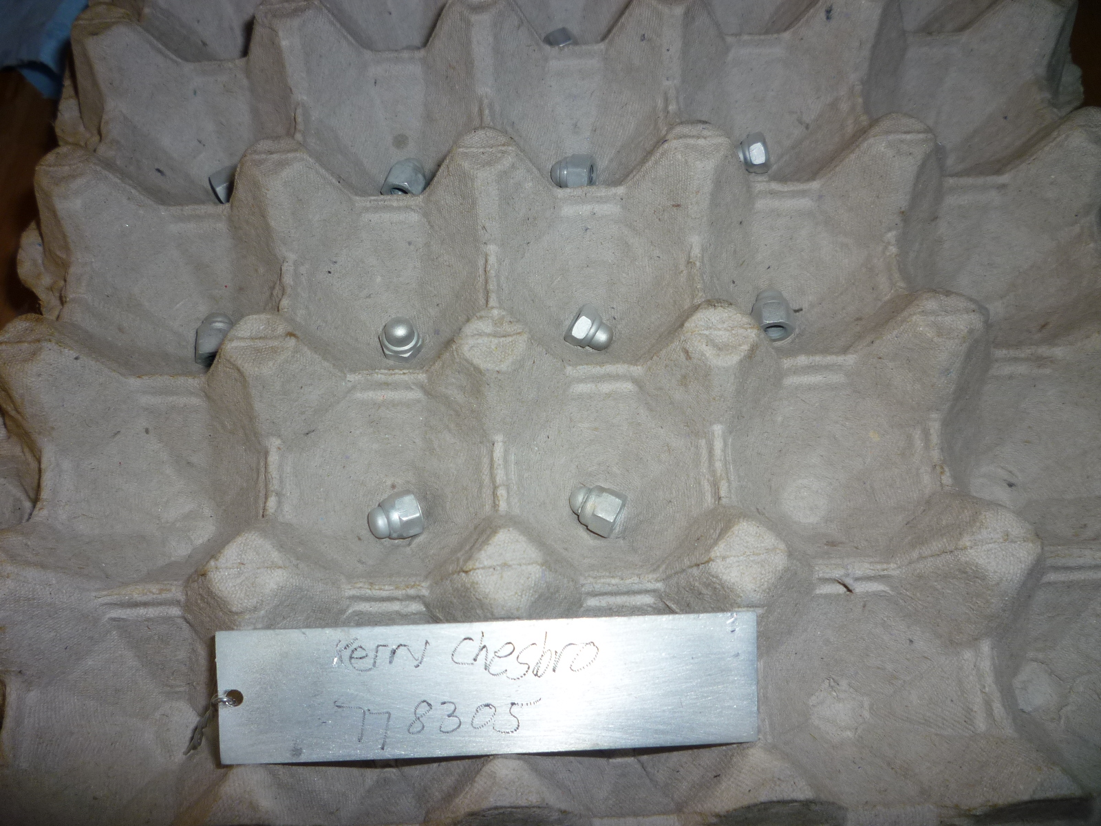
The parts that were out for the cadmium plating came back. Since these were lots of little items, I was wondering how they would package them. They came back nestled in a stack of egg cartons, one part per indentation. Here you can see the acorn nuts used on the valve covers along with the etched plate with my name and order number so they can keep track of the items when they come back out of the large tank.
Several of the parts in the linkage get cad plated. As shown, the socket ends and the balls that screw on are among them. The ball ends that are riveted on get black oxide like the lever they are attached to.