Studs
One problem with putting together a car from boxes is that the people who took it apart didn't necessarily save everything that they should. In particular, most of the studs had been removed from the engine and not kept. That's not a problem except that one doesn't necessarily know what dimensions the original studs were.
The head studs weren't a problem as a friend was in Italy and just asked for outside plug 250 head studs and brought them home for me. The valve cover studs are standard and easily measured. But when I went to do that, I found that the valve covers weren't the correct ones for these heads. When I went to count, there were 5 holes on each side in the covers, but six stud locations in the heads. Got that sorted out and was able to buy the studs from McMaster-Carr.
There is a another PF coupe undergoing restoration locally, so I was able to measure all of my missing studs to determine what I needed.
Most of the studs for the block are special. They have fine threads on the exposed end for the nut, but coarse threads where they screw into the aluminum block, head, etc. This gives more bite into the softer aluminum. I ended up having Dennison International make the 15 or so studs that I was missing. I had made a good contact down there when I helped out on their restoration of the 'Golden' 330 GT. I asked how they make the studs. They start with a bolt with the correct fine thread that's long enough. Then, cut it to length removing the hex head. After that, they put rolled threads on that end matching the coarse thread requirement.
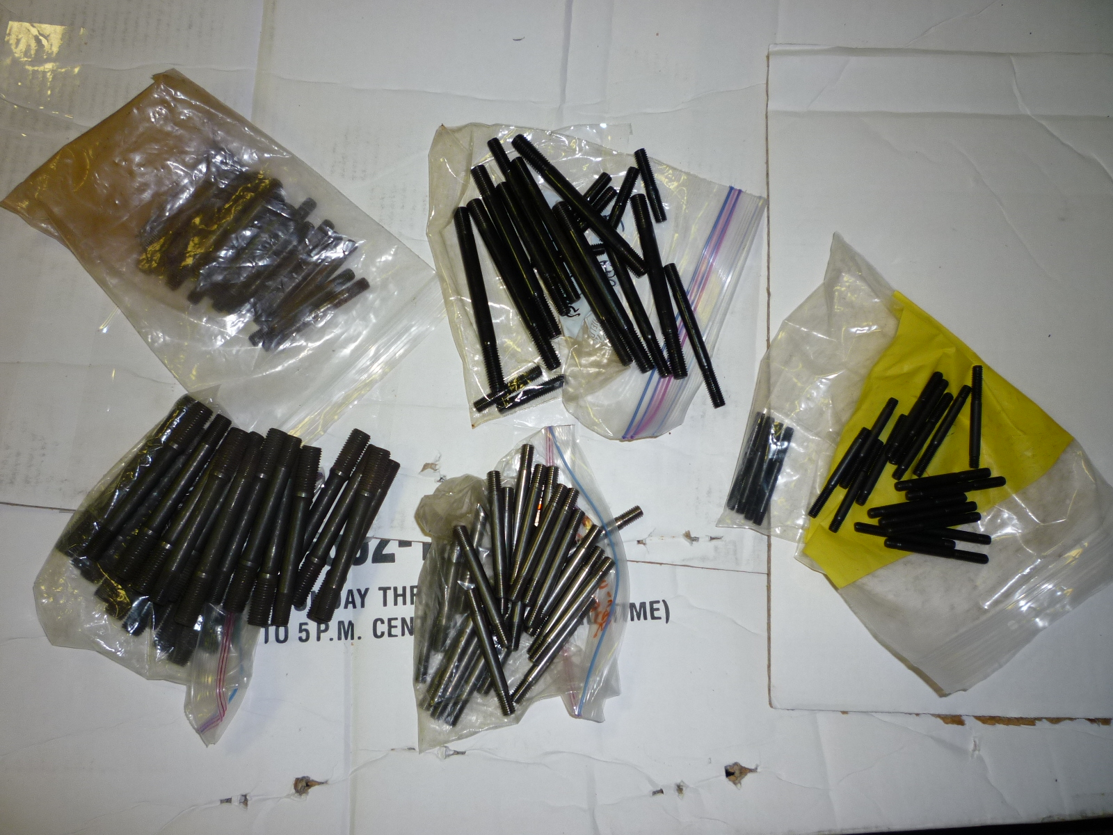
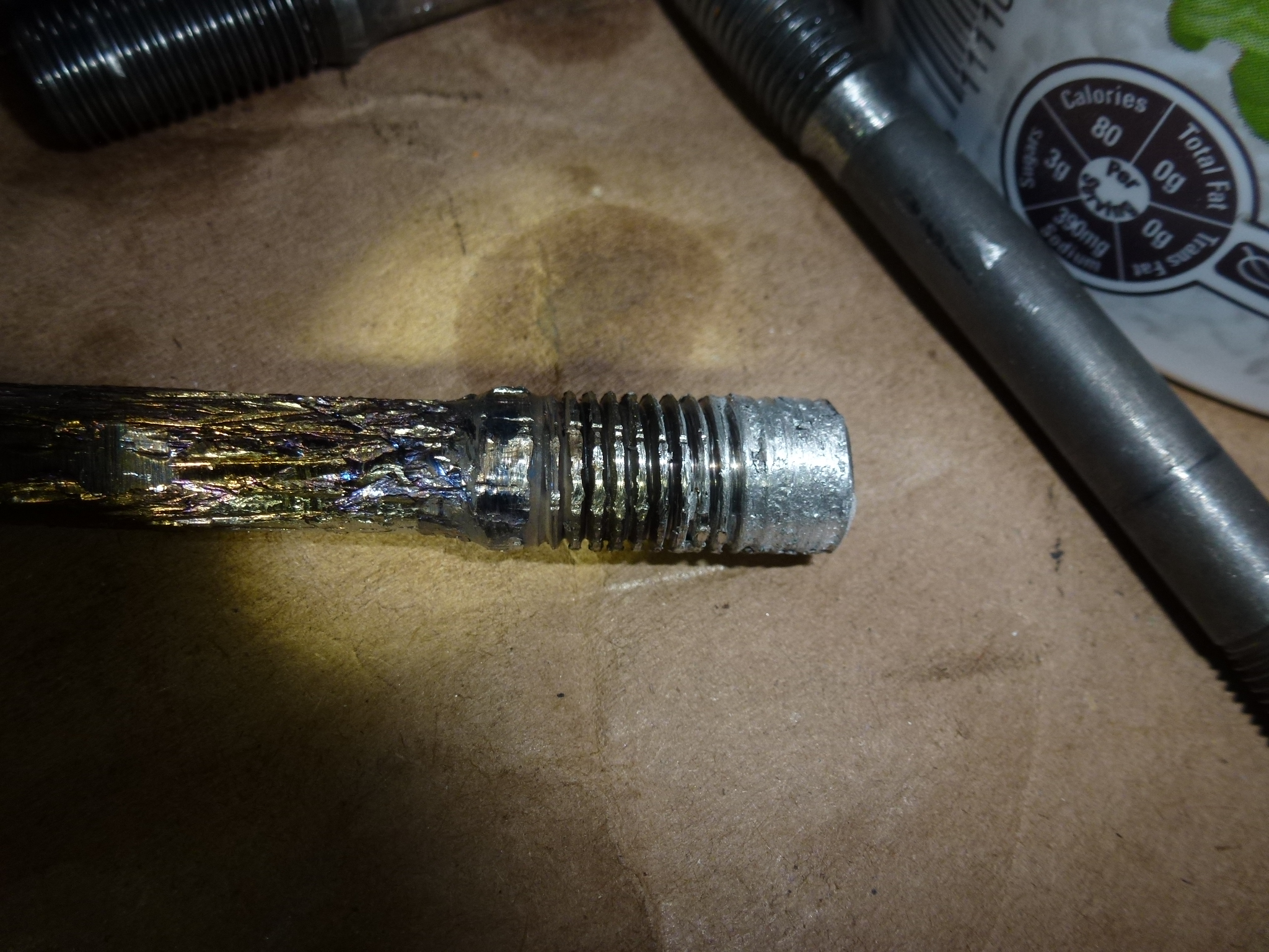
Here are some of the studs I needed.
It turns out that I made an error on the manifold studs. These are 10mm with 1.5mm threads on the block end. I presumed that they would have the fine machine threads (1.25mm) on the other end, but instead, they are more finely threaded than that with 1.0mm threads. Since Ferrari used special acorn nuts, I had to have those studs remade correctly as the acorn nuts are not available in the 1.25mm thread.
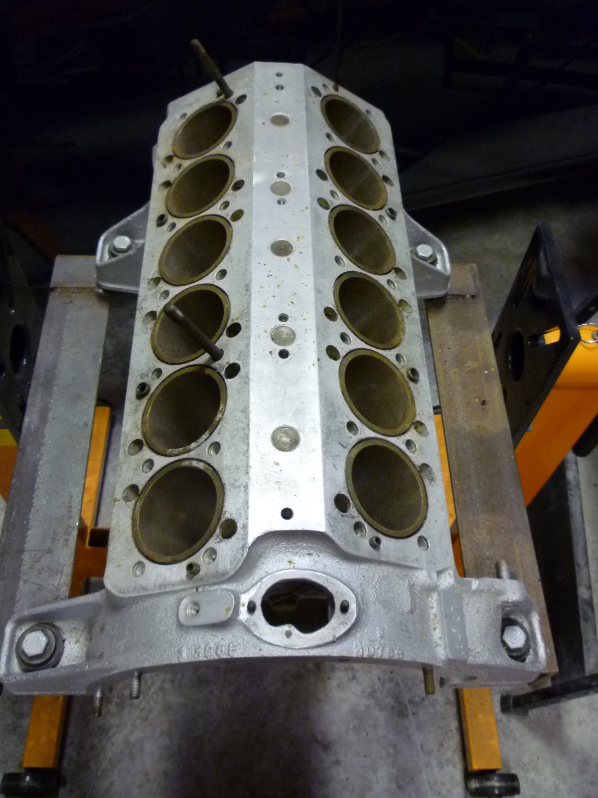
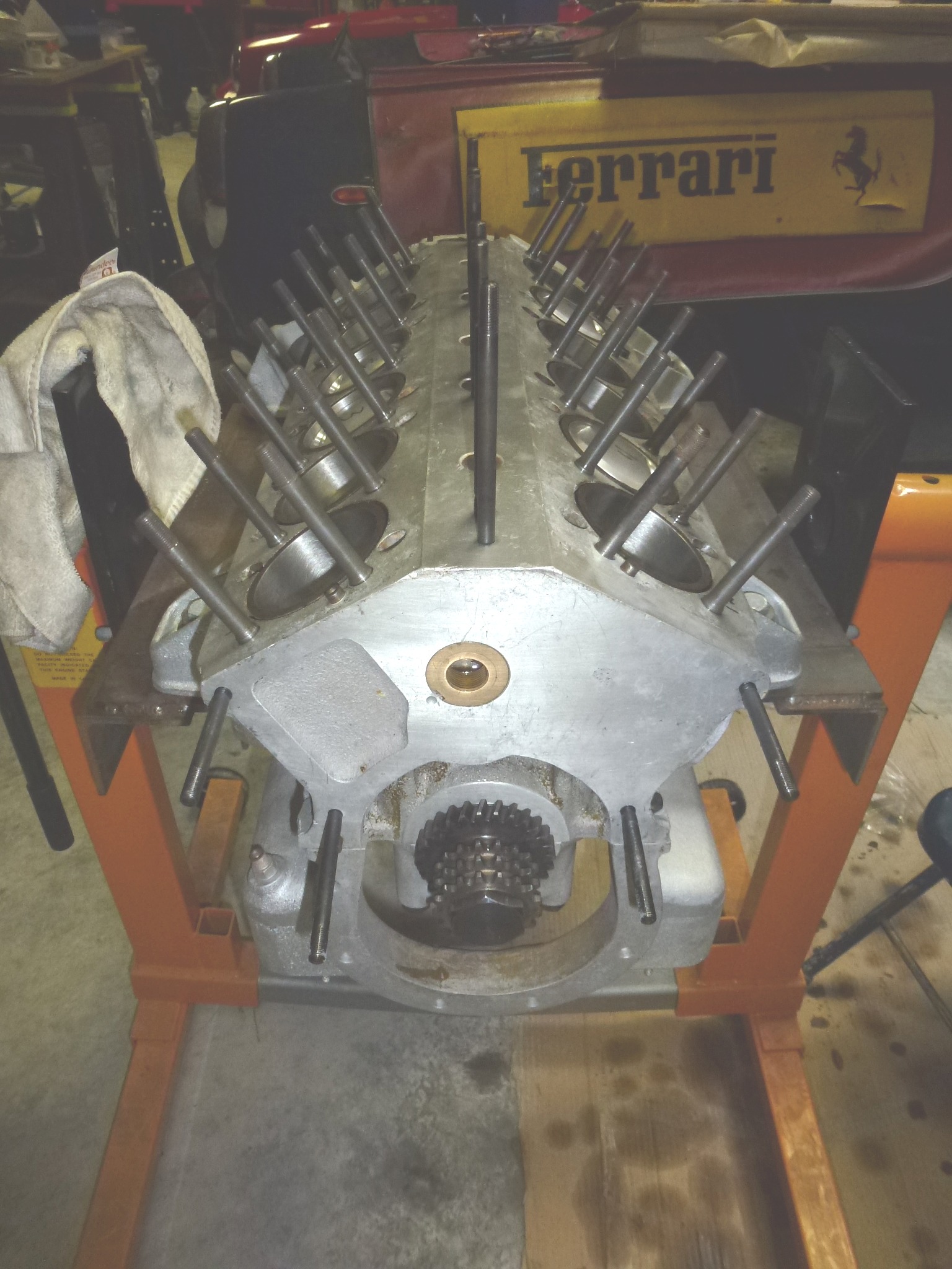
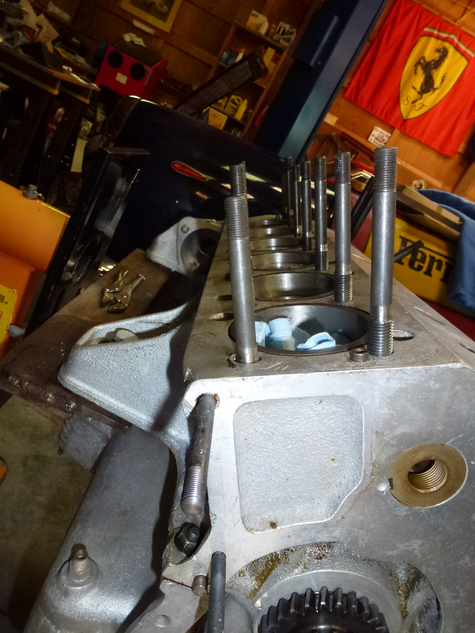
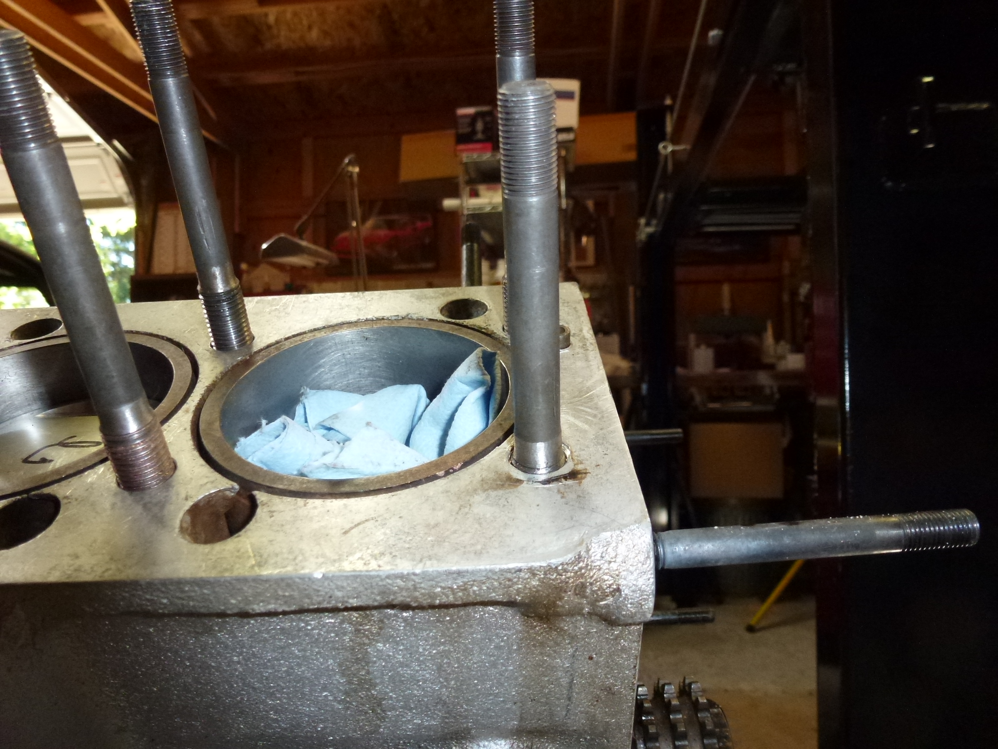
It took several hours to install all of the studs. All of the newly made ones had to be measured and cut to length. The block doesn't look so naked with all of the studs installed.
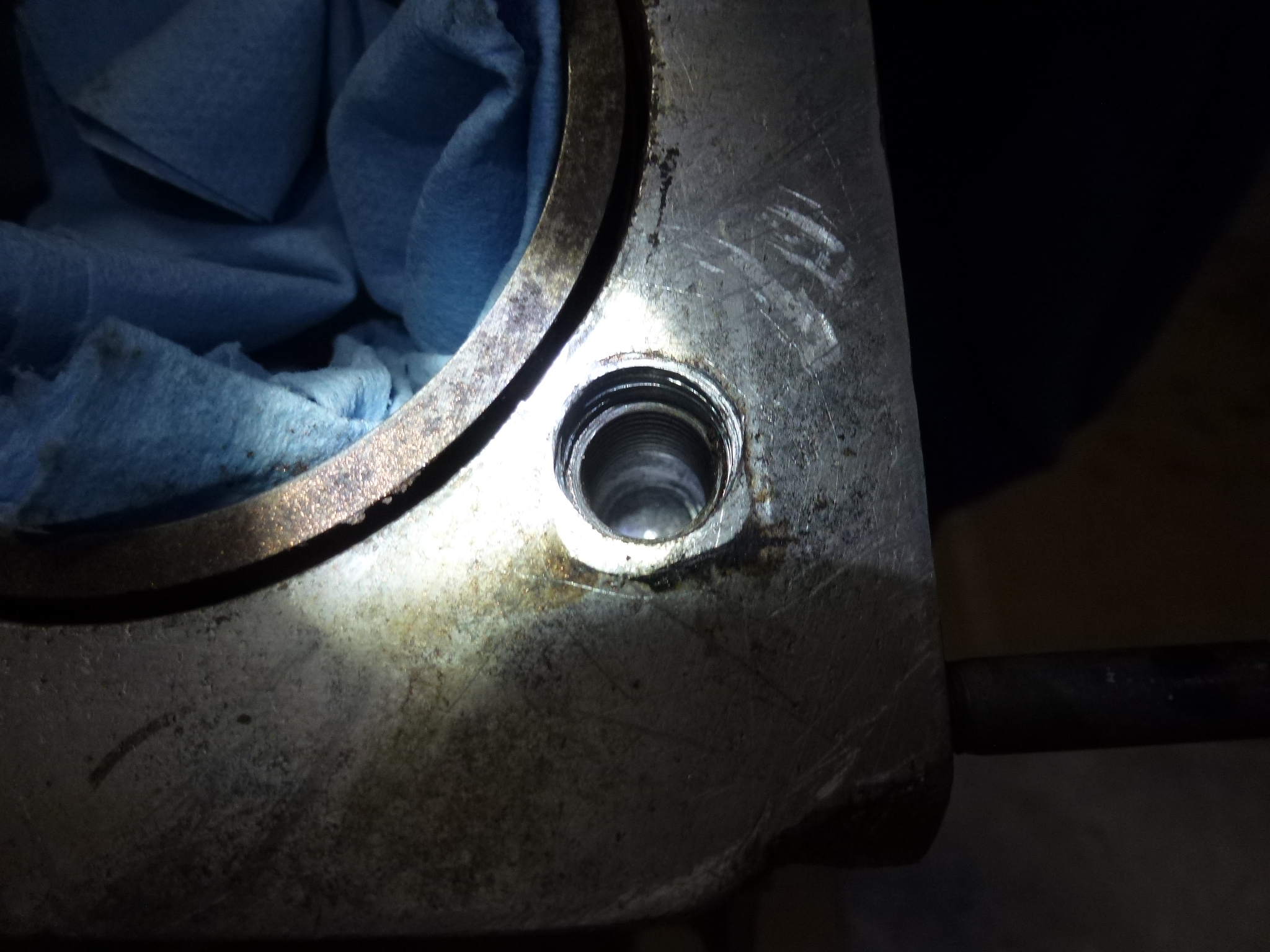
After all of the studs were in place, as I was flipping the engine, I noticed that the head studs didn't seat down into the block correctly.
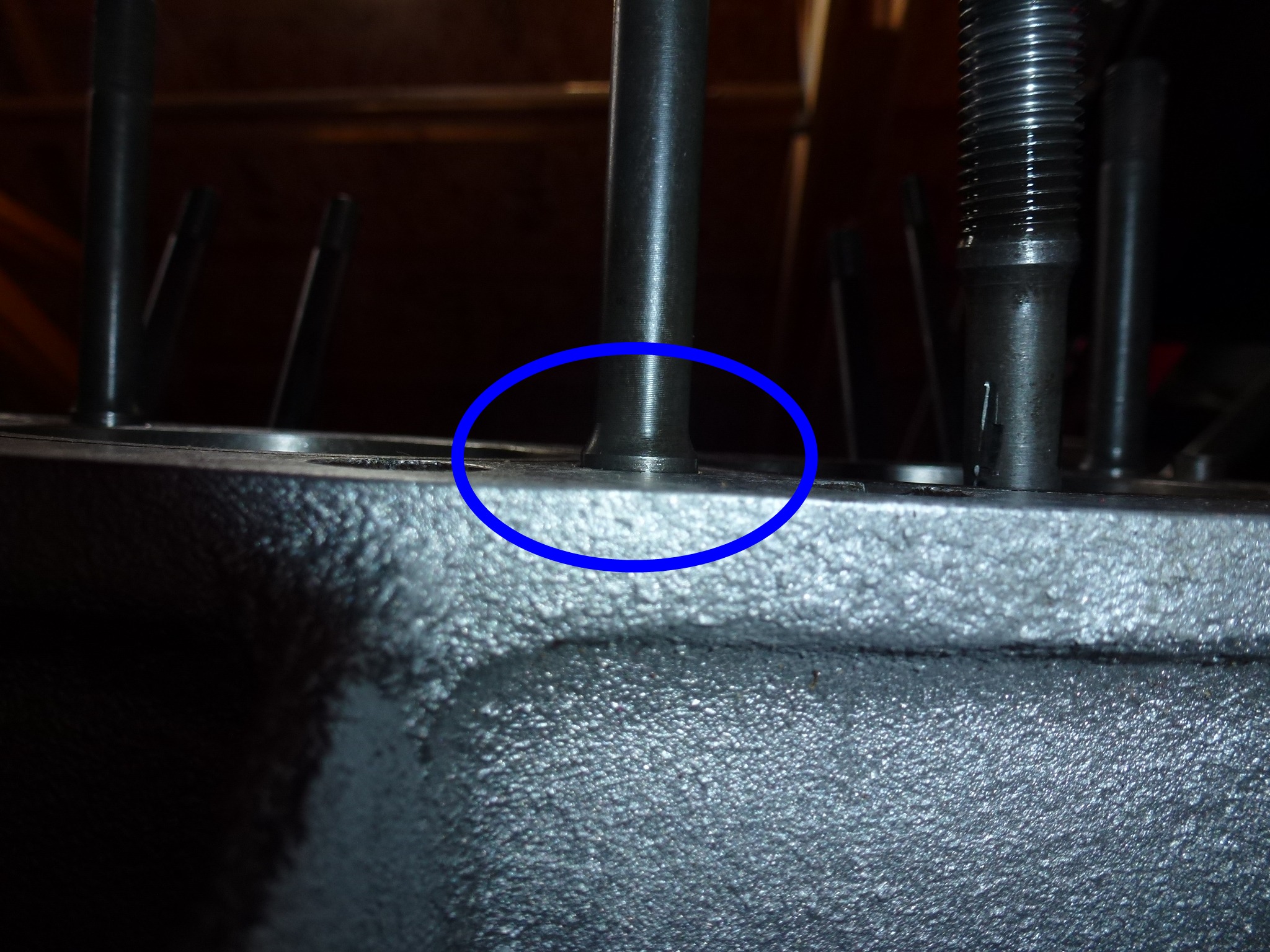
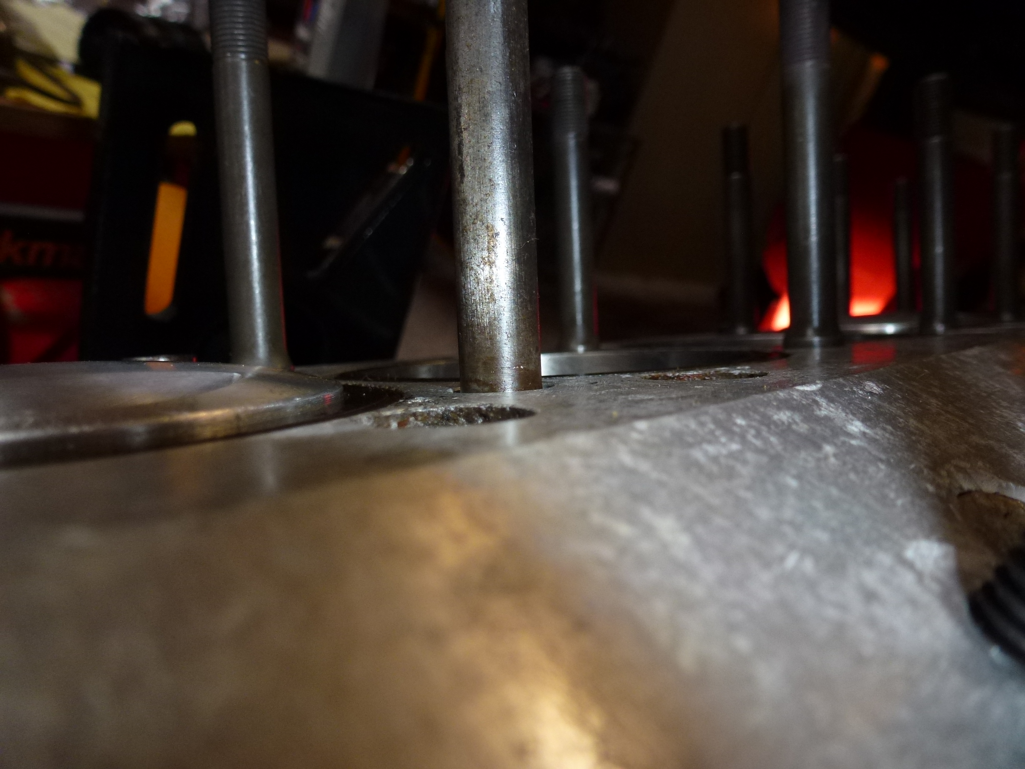
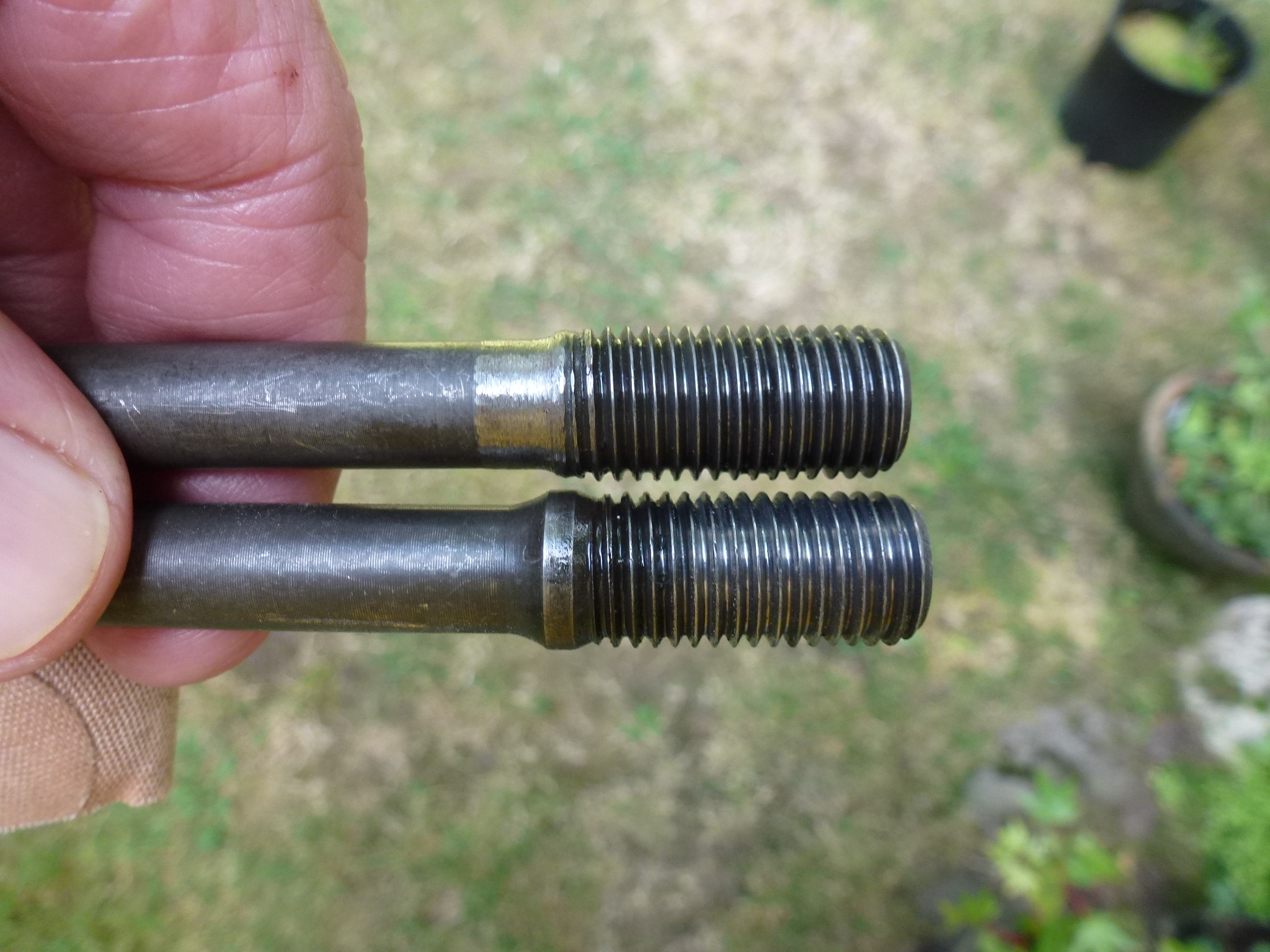
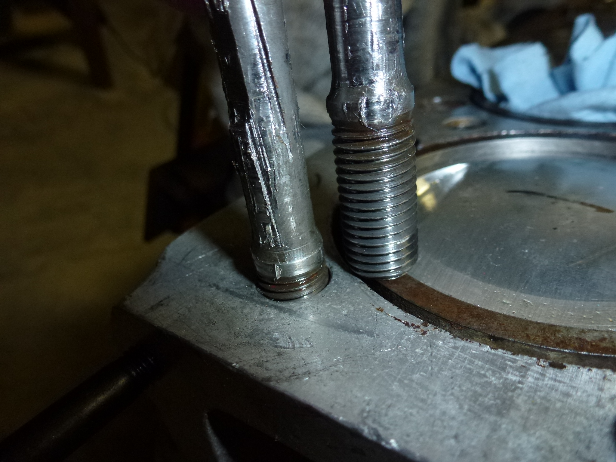
You can see how the shoulder and neck on the stud are protruding above the block deck compared with the old stud in the right picture. I did some measurements and it wasn't clear if the stud was bottoming on the threads or the shoulder was stopping at the threads at the top. After a discussion with my machinist, it was decided to grind away the shoulders so the head could fit down over the studs. Here's a stud that's been ground down along with an untouched one. I was worried about weakening the stud, but was told that by grinding, no sharp edges or indentations would be left to cause a problem.
Now my last problem is one stud that I couldn't remove. It was one I had shortened the thread by a couple of millimeters to see if it was bottoming or not. There must have been a burr left, as it stopped going in about 1/4" from the bottom and now I can't remove it. So I'm waiting to hear how my machinist suggests we get it out. As you can see, it has a bunch of turns to unscrew before it would be out. The only good thing is that there were two old studs that were never removed, so I have a couple of spare studs.
It was suggested that I heat the block to 350° F to expand the threads in the block so the stud could be removed. My neighbor brought over this welding tanks and a rosebud tip. We used an instant read cooking thermometer to read the temperature by the stud
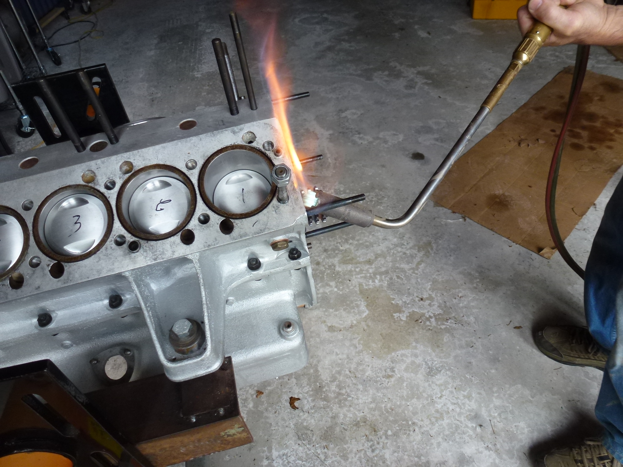
Luckily, the stud in question was in a corner, so much easier to heat around it. Unluckily, the stud did not come out very nicely. The stud threads were galled and pulled most of the aluminum threads with them.
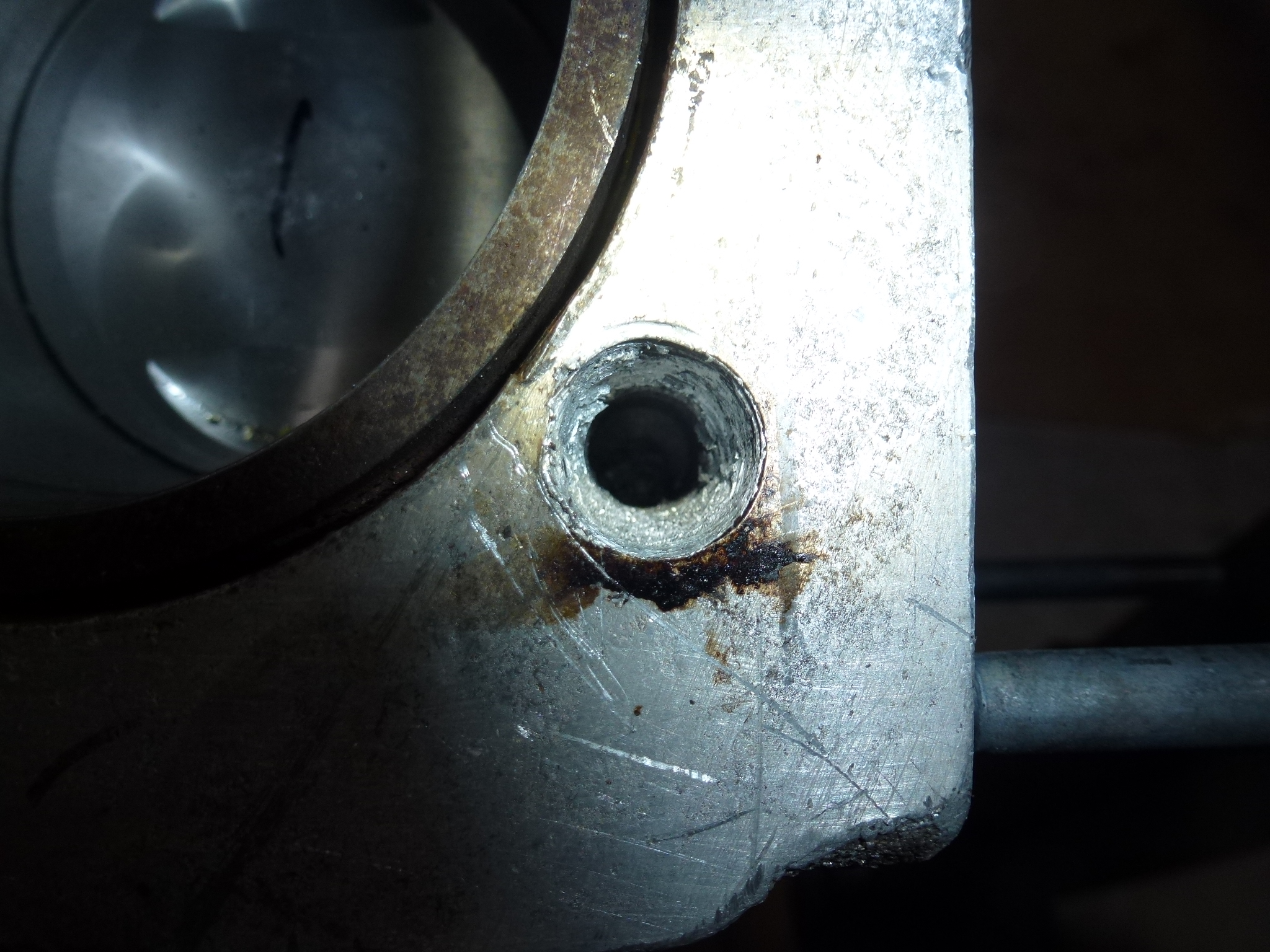
I cleaned out the hole and ran a tap down into the threads that were left. I could screw in a new stud, but it wasn't perpendicular to the block. So the next step will be to drill and install a HeliCoil insert. I would prefer to use a thick wall insert, but as you can see, there isn't room by the piston liner.
Getting the hole drilled and tapped perpendicular and in the right place will be tricky. My neighbor has a portable drill press mounted on an electro-magnetic base. So the plan is to take a plate of 1/2" steel, transfer the stud hole locations onto it using a transfer dowel from the stud holes in the head. Then drill holes, using a machinist drill press, in four of the stud locations for 12mm bolts to be able to fasten the plate to the head. The hole for the screwed up location will be drilled the correct size for the HeliCoil insert tap. There also needs to be a couple of holes to fit over the alignment dowels in the block. Once that is done, bolt the plate to the block and clamp the portable drill press in the proper spot, using a short length of drill rod to fit into the pre-drilled hole in the plate over the bad location. Then, we'll drill out the block and tap both the steel plate and block at the same time, without moving the press or removing the plate. I'll also have to whack off the bottom of the HeliCoil tap to make a bottoming tap in order to tap far enough down for the HeliCoil to be inserted properly. I found that HeliCoils in blind holes, need to have a bottoming tap used. If there is any taper left at the bottom of the coil, it will insert properly, but leave tapered threads on the inside. Thus the bolt or stud you are inserting will bind in the tapered area.
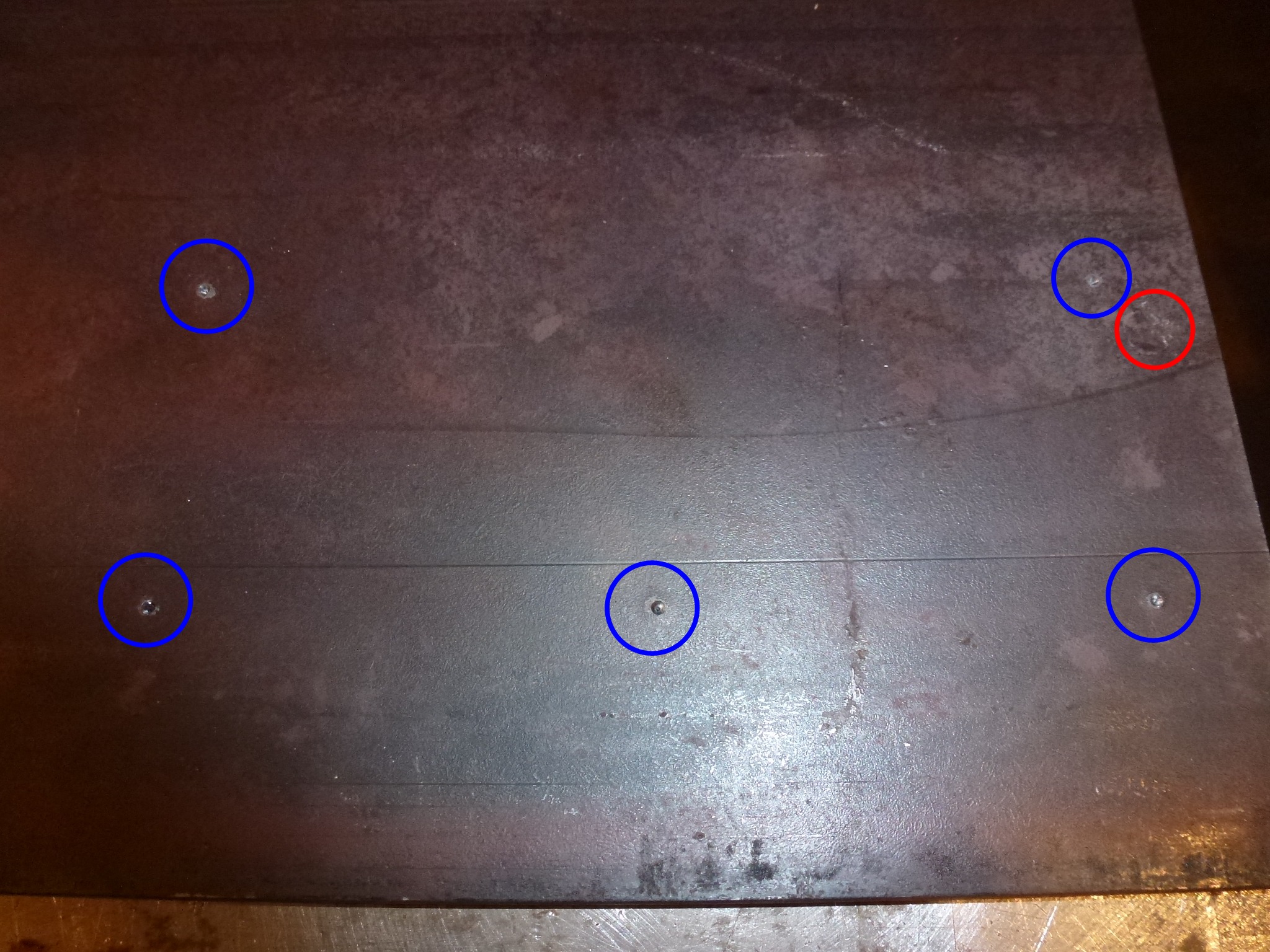
I picked up a sheet of 1/2" plate 12"x11". To transfer the stud holes in the head to the plate, I used a transfer dowel to mark the locations. You can see the five stud locations circled in blue. The red circle is the location of an alignment pin in the block that also needs a matching hole in the plate. Note, the holes are actually in straight lines at right angles, but the wide angle camera lens distorts the picture.
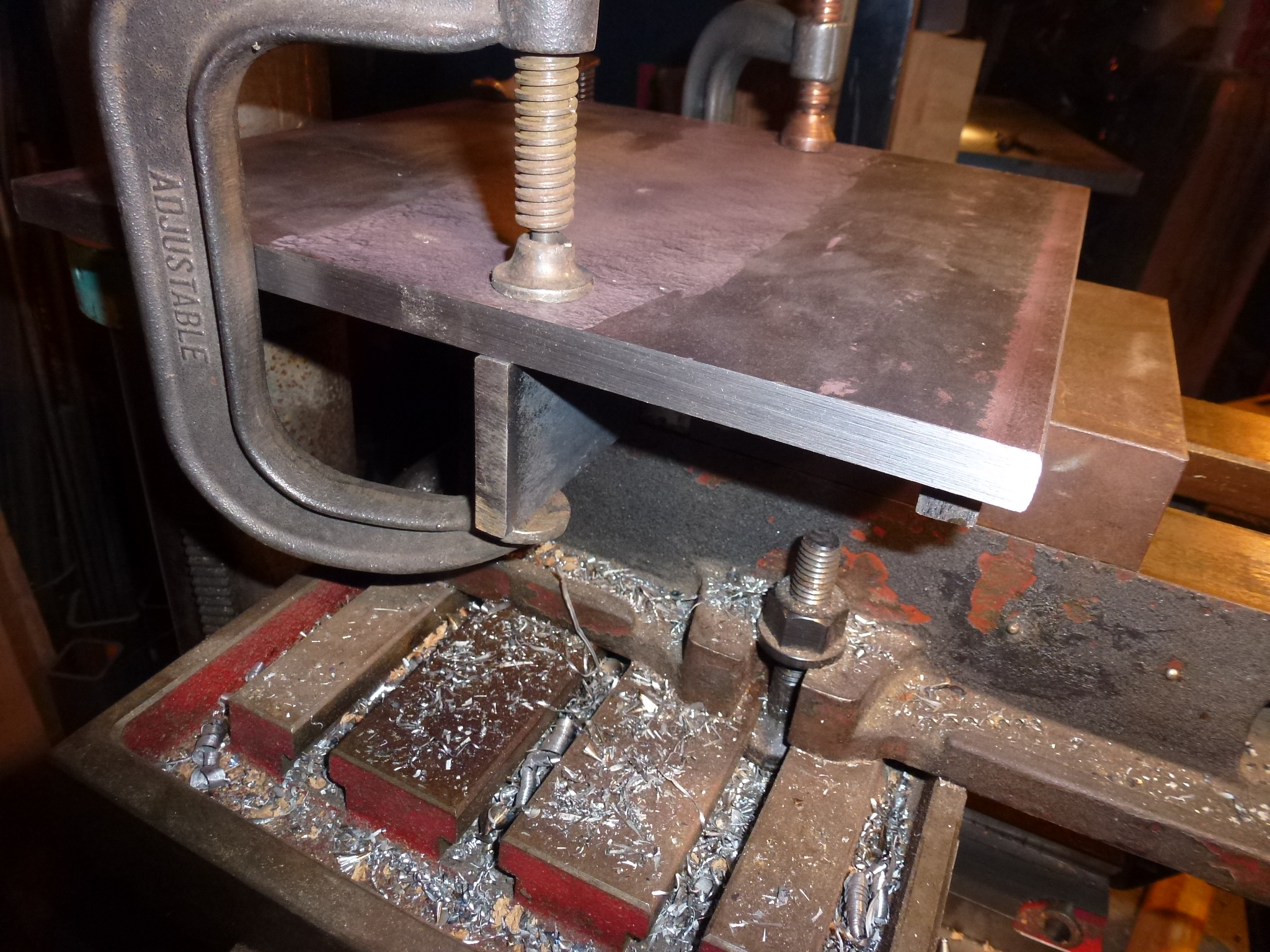
Once the locations were marked, measurements were made to a thousandth of an inch. Then a flange was welded onto the plate so it could be mounted in the machinist vise on the drill press. Here it is being aligned prior to welding.
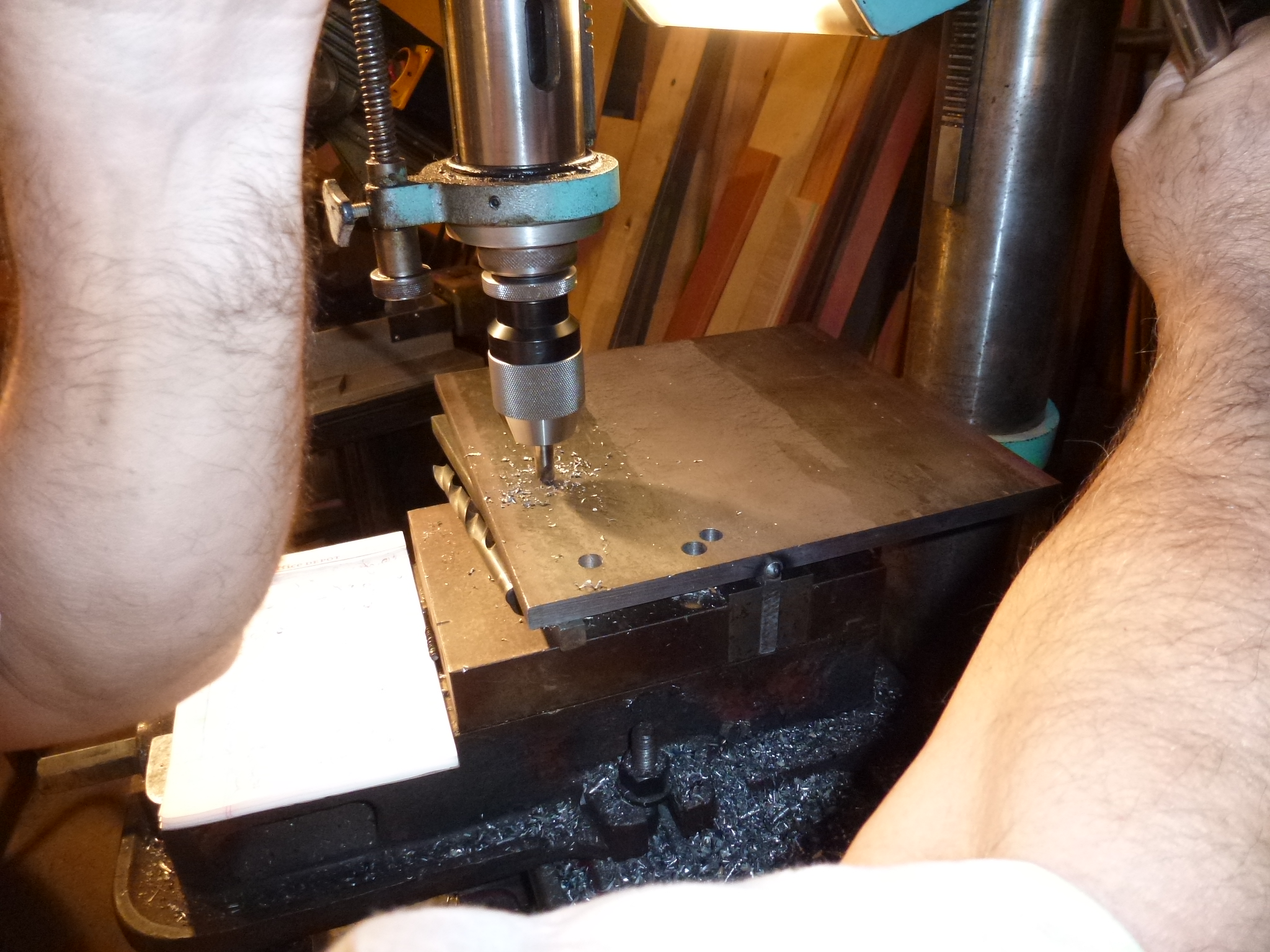
Once mounted for drilling, the corner was indexed to zero, zero, so we could always go back and re-measure if needed. The first hole was the bad stud location and everything else was indexed off of that hole. Here you can see a spotting bit being used to set up for drilling. For those who don't know about a spotting bit, it is a thick bit (1/2") with a small tip (1/8") and then a cone portion. The bit can't bend due to its size and the small tip starts a pilot hole exactly where it is aligned. Then the cone portion cuts a bevel cut large enough that the actual drill bit can't wobble as it starts. Of course, this is only useful in a beefy drill press with a vise that doesn't allow the drill or work to move around.
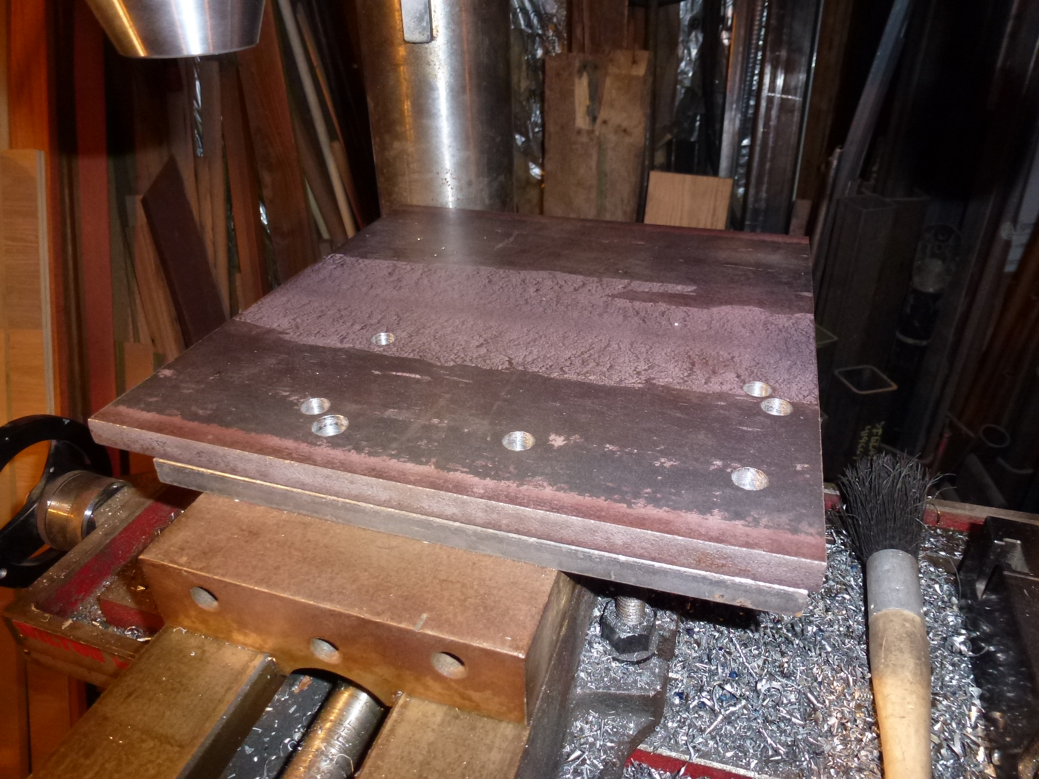
Here is the plate will all of the holes drilled.
Then we removed the welded on flange and cleaned up all of the burrs. The HeliCoil kit should arrive tomorrow so we can finish this project.
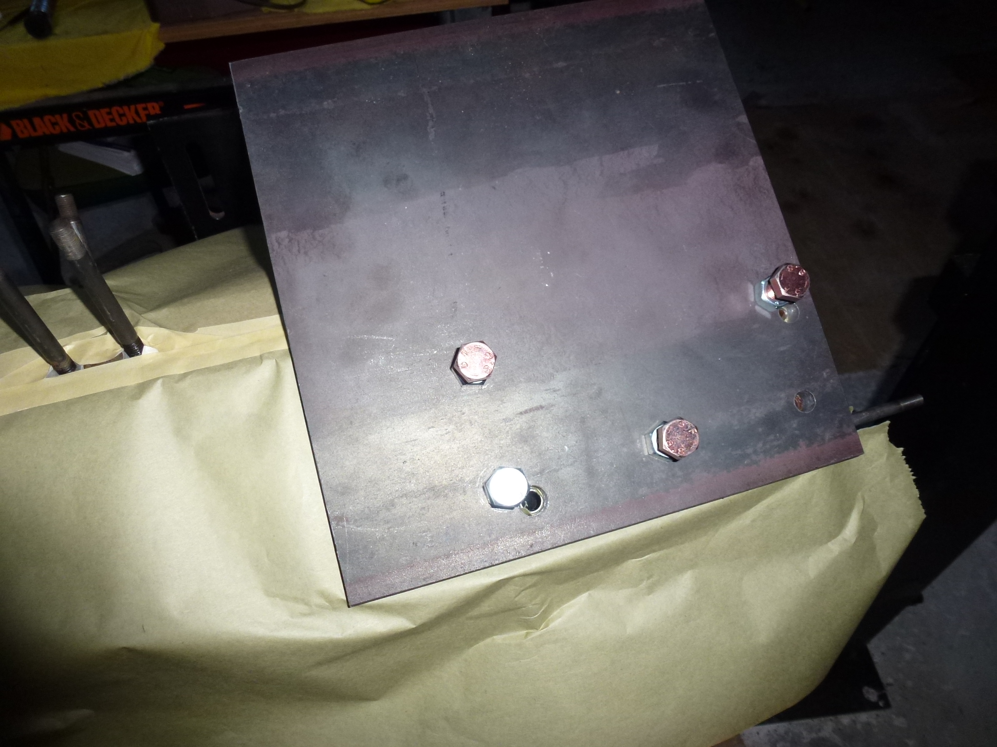
The HeliCoil kit arrived, but I realized that I had mis-measured the thread pitch. I had ordered a 12x1.25mm kit, but needed a 12x1.5mm one. So had to return the one and get a replacement. Once it arrived, we were back in business. First, I covered both head areas with paper and taped the sides, so no metal chips would end up in a cylinder, water jacket or oil port. Then I installed the plate.
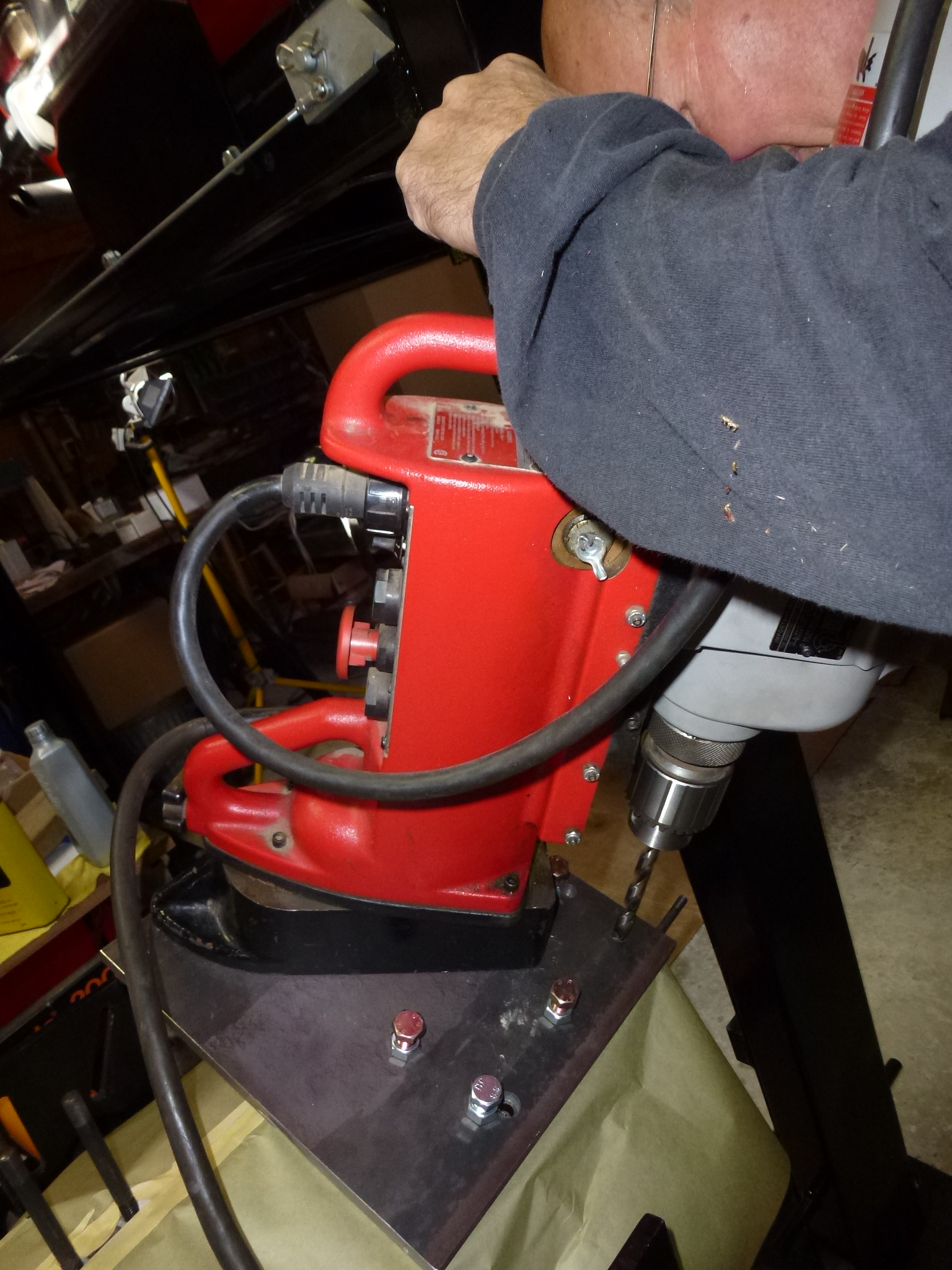
I had also ordered a 31/64" drill rod that matched the hole we drilled for the bad stud. A chunk of this was put in the magnetic drill so we got it aligned exactly with the drilled hole. Since I had looked at the specs for the wrong HeliCoil kit, the new kit used a slightly larger drill, 12.5mm (about 8 thousands larger), so a slight amount of the steel plate was also re-drilled. Then, carefully measuring the depth, the hole was extended into the block. As you can see, the magnetic mount drill press is a beefy machine.
Once that was done, we put the tap into the drill press and used it at an extremely slow speed, to tap through the steel plate. After that we hand tapped the threads into the aluminum block. With the tap threaded through the ½" steel plate, I wasn't worried at all about the tap going in crooked. Next was putting in the actual HeliCoil and removing the tang at the bottom.
Finally, I lightly screwed in the studs for the head to check for alignment.
The new stud was exactly right while a couple of the other studs will need a bit of fiddling to get the head on.