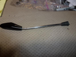
Headlight Switch Stalk
One of the things that had broken over the years was the headlight switch stalk. It had broken just outside of the steering wheel housing where the end of the metal stalk is embedded in the plastic switch part.
I tried to epoxy it a couple of times, but it would eventually break again. I finally found a place that casts parts for toys in both metal and plastic. The original time estimate was about 3 weeks, but it took more like 4 months before I got the finished part. They took both the handle and the broken off part (switch section) and made a mold that included the handle. Then they removed the broken stub from the handle and cast the new part right on the handle. They could also cast just the plastic end by putting in a substitute handle without ears so it could be removed after the casting. That way if it broke again, I wouldn't have to send in the handle, but just have them make up an extra end from the existing mold.

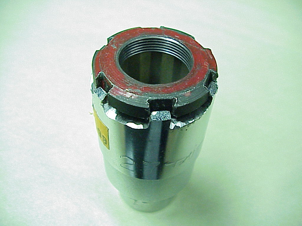
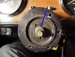
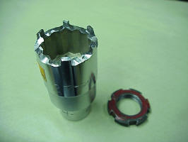
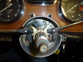
Of course it wasn't quite that simple. To get at the part to remove it, you have to remove the steering wheel, the horn button and the hub that the steering wheel bolts to. The hub is held by a nut with slotted sides (that accept a tabbed washer that locks it in place).
I used a die grinder to turn a 27mm socket into the notched socket necessary to remove the nut.
The hub is positioned on the shaft with a woodruff key. The first time I took it off, I didn't pay attention to the location of the woodruff key and it was on the down side of the shaft. The key kept falling out and sliding down into the switch assembly when I was trying to put the hub back on. I finally jacked up the front end so I could turn the wheels and have the key slot up.

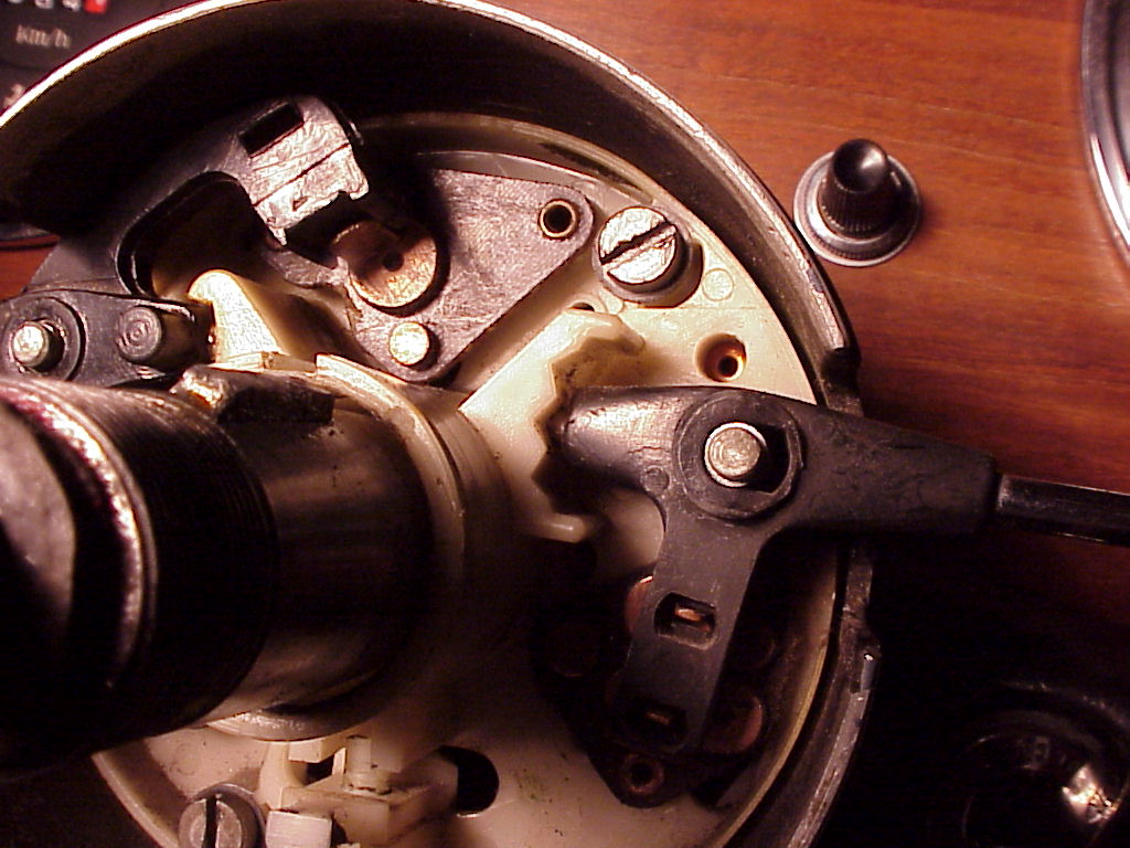
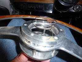
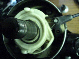
After the hub is off (using a small gear puller), the insides are pretty formidable.
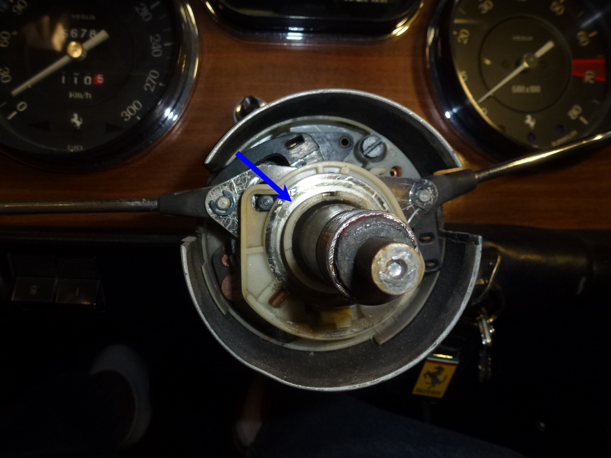
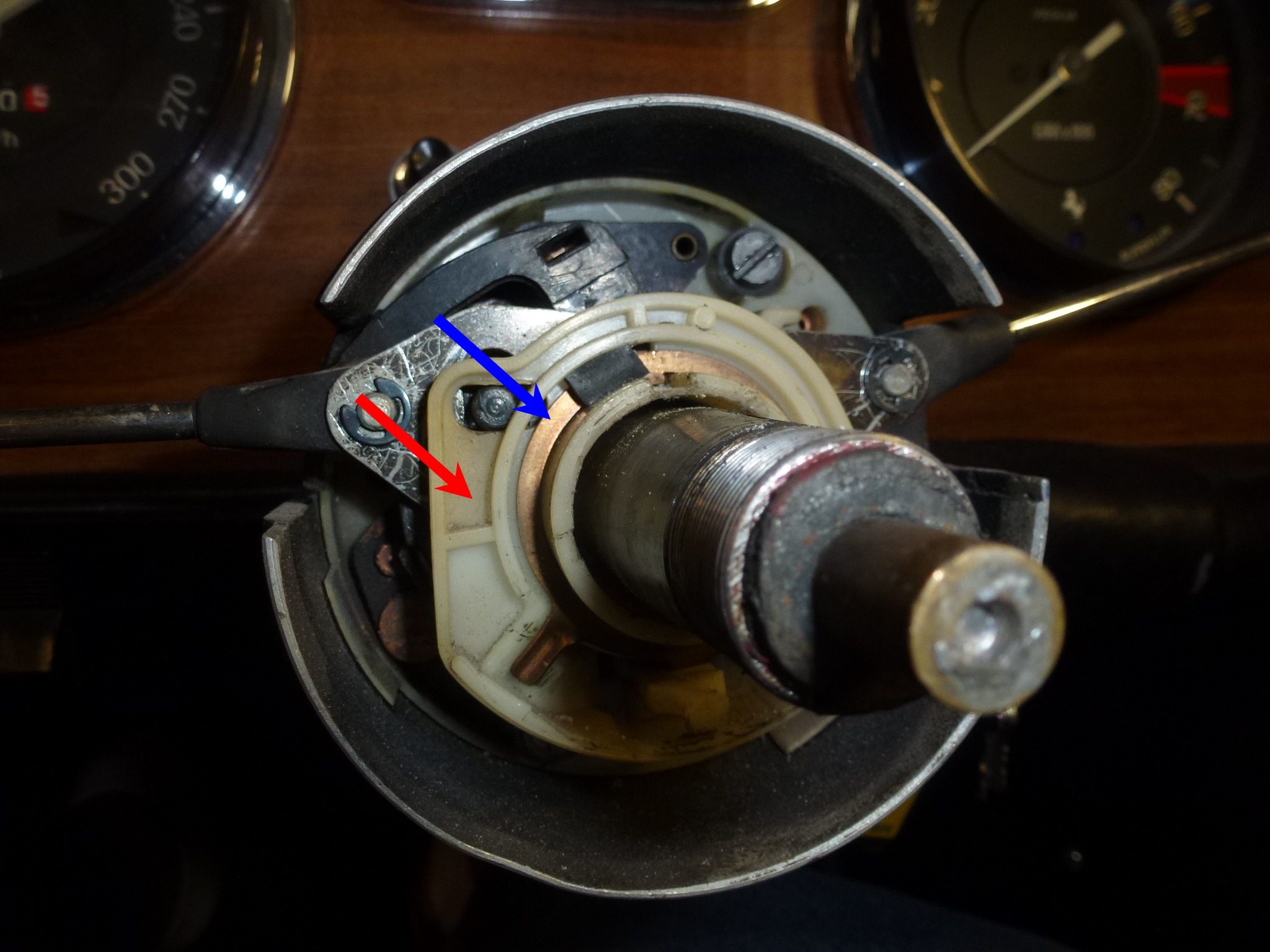
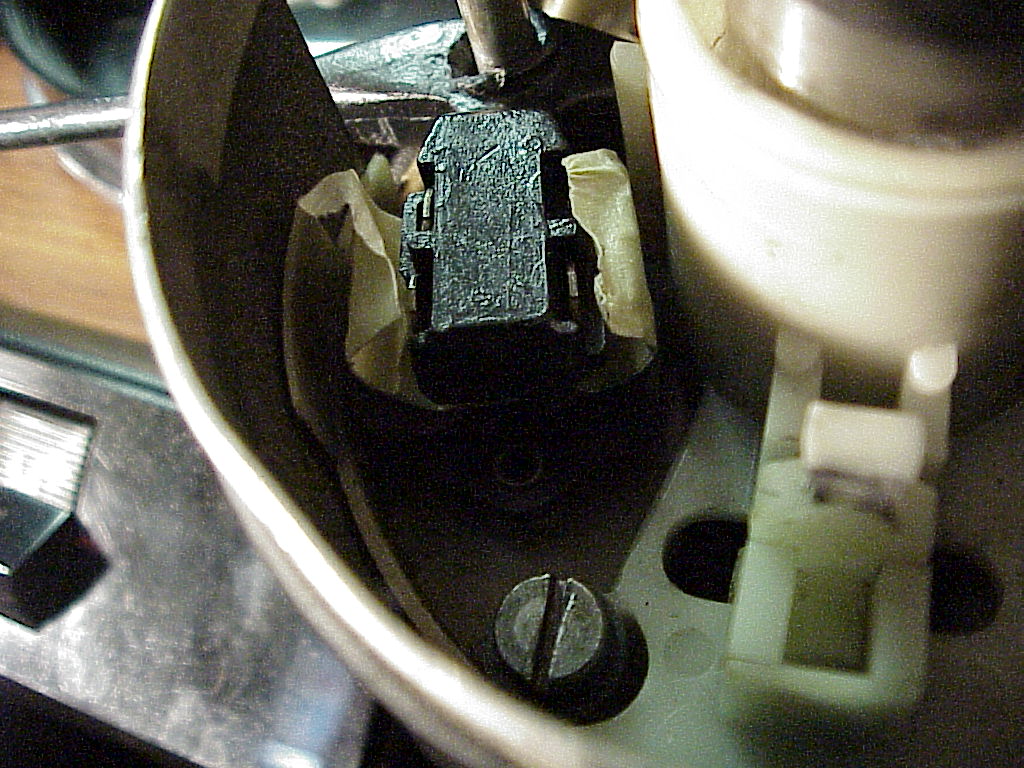
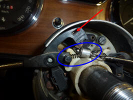
The first layer deals with the self-canceling feature of the turn signals. Note the arrow that points to an arrow on the plastic ring. This needs to point to the top of the steering wheel when re-assembled for the self canceling to work properly. Underneath that plastic piece is another one with a large copper washer like piece. The copper piece has a tab that holds the shaft for the self canceling ratchet. The ratchet is the vertical piece in the bottom center of the next picture (see arrow). It has a spring that is attached down underneath everything. Try to remove the copper washer and tab without removing the ratchet or spring. If the spring does come off, then you have to loosen the whole assembly, wiring harness and pull it out of the column housing enough to re-attach the spring.
After removing the first layer, one gets down to the switch layer.
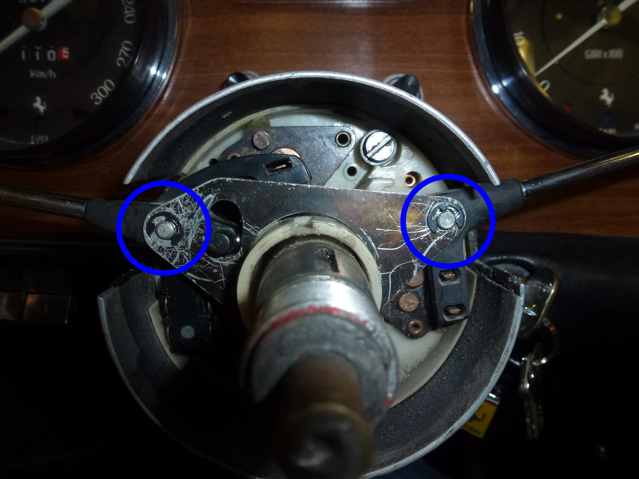
You remove the black metal retainer (held by two C-washers on the studs that hold the stalks) and then you are at the actual switches. I would recommend putting the C-washer back on the side that you aren't taking apart. This will prevent that arm from being accidentally dislodged (not that's every happened to me :).
As you remove each stalk, be very careful to not let the detent spring and ball bearing fly out. I use a pickup magnet to catch the ball and spring as I ease the stalk out of the detent area. By moving the stalk between positions as you ease it up you control the removal much easier. Here you can see the ball bearing at the end of the stalk ready to be caught by the magnet. The stalk on the right is the wiper stalk and it's on low speed.
|
|
 |
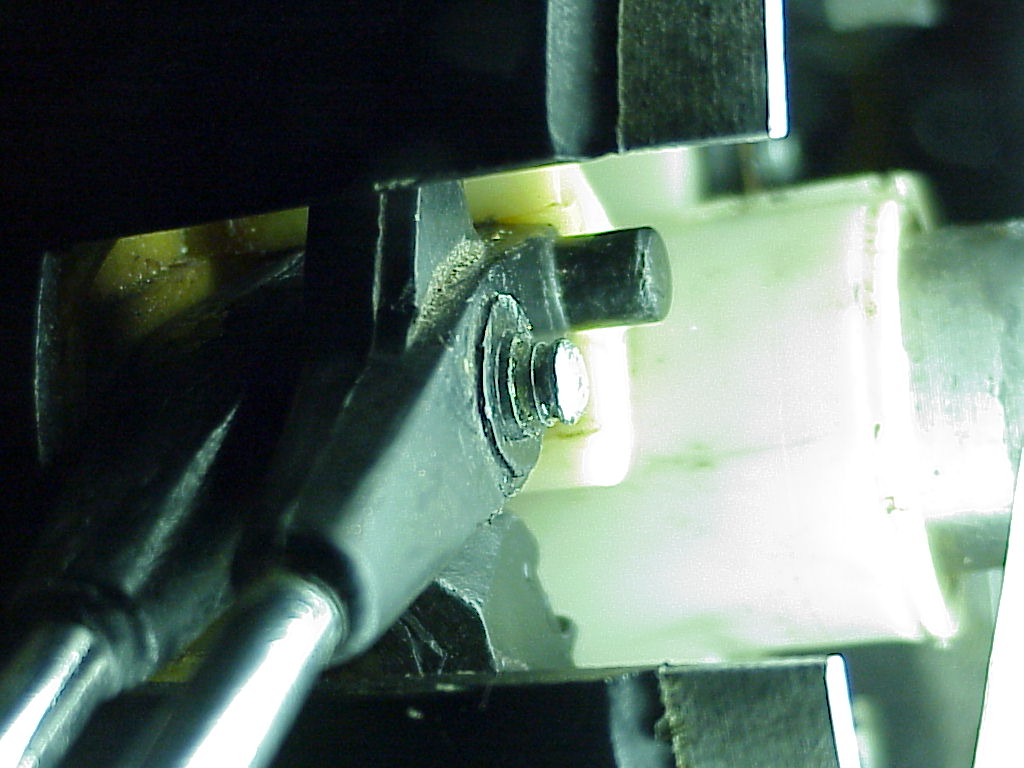
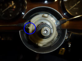
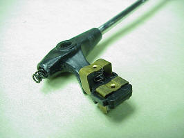
Now you can see the contacts that make all of the electrical connections. The lower left ones are for the headlights, the ones at the top are the turn signals and the wiper ones aren't visible, but are in the dark area on the right side. A good cleaning and a little sanding with emery cloth will help keep the connections in good shape. The arrow points to the switch that flashes the headlights. As you pull the headlight switch handle towards you, the other end pushes down on that nylon button which actuates the flash switch.
Putting the handles back on the switch assembly is also an exercise in futility. Each handle has a spring loaded ball bearing that clicks into indent places in the assembly. This is what holds the switch in each location. Each switch end also has one or two U-shaped pieces of copper that make the actual contacts. These are also spring loaded so they push down on the contacts. So you have 3 spring loaded pieces that all want to come apart as you are trying to put everything together. You can tape down the contacts, but the ball bearing has to be loose. I had the it fly off several times when I was putting trying to put the arms on. One time, I couldn't find it, so I emptied the shop vacuum, vacuumed the whole car, including every nook and cranny. After that, I went through the canister and found the ball bearing. If you do lose one, they are 3/32" in diameter and can be obtained at a good hardware store.
Here you can see the contacts taped with two layers of masking tape (stuck together so they won't stick to the either side). The spring where the ball bearing goes is just above the center of the picture.
This time, I thought that there had to be a better way to push the spring in with the ball bearing at the same time you push the hold stalk down so the spring and bearing are caught by the detents in the plastic. I ended up making a small tool out of a short piece of 3/16" brass rod. Then, using a 3/32" drill, I drilled a small cone in the end of the rod, stopping just when the drill would start an actual hole.
This worked like a charm, three for three (now, about 20 for 20) with no flying bearings. You just put the bearing on the plastic near the end of the stalk, use the tool to push it against the spring and push the whole stalk down. The bearing stays on the end of the tool until it snaps into the detent area. Here's one stalk in place with the masking tape holding the U-shaped contacts ready to be removed.
A while ago, there were some sparks from the hub area and the headlights stopped working. This was why I took everything apart now. Somehow the U-shaped contact pieces had come loose from the headlight stalk and one of the springs shorted things out, burning it in two. I also noticed that one of the other springs was also broken, so another trip to the hardware store. Century C-520 3/16" x 7/8" springs were the right size and about the proper tension. I had to cut them down to 1/2" long, but put the cut ends into the plastic hole in the stalk where they won't matter.
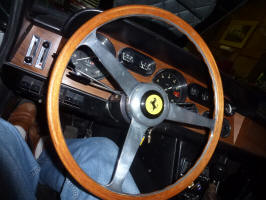
So everything is all back together, but since the steering wheel is off, I'll take the opportunity to buff and polish it and the hub around the horn button.
Yet again, the high beams stopped working. Since I seldom drive the car at night and then usually only in town, I ignored this problem for several months. However, I am entering it in a concours so I thought that all of the lights should be working.
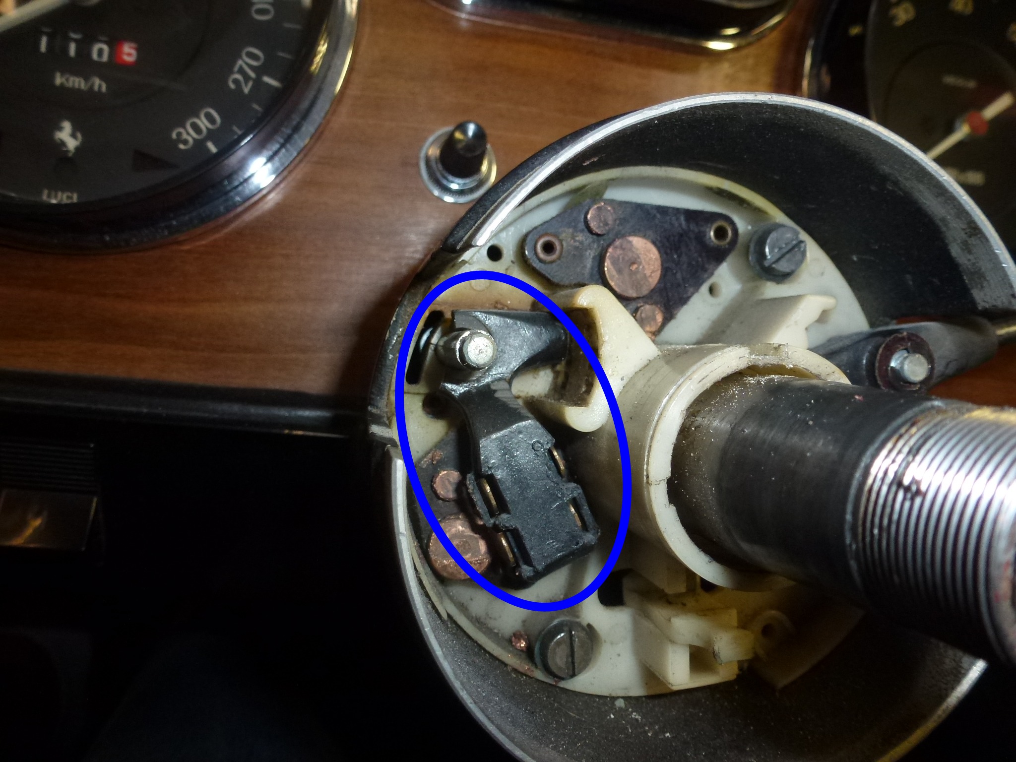
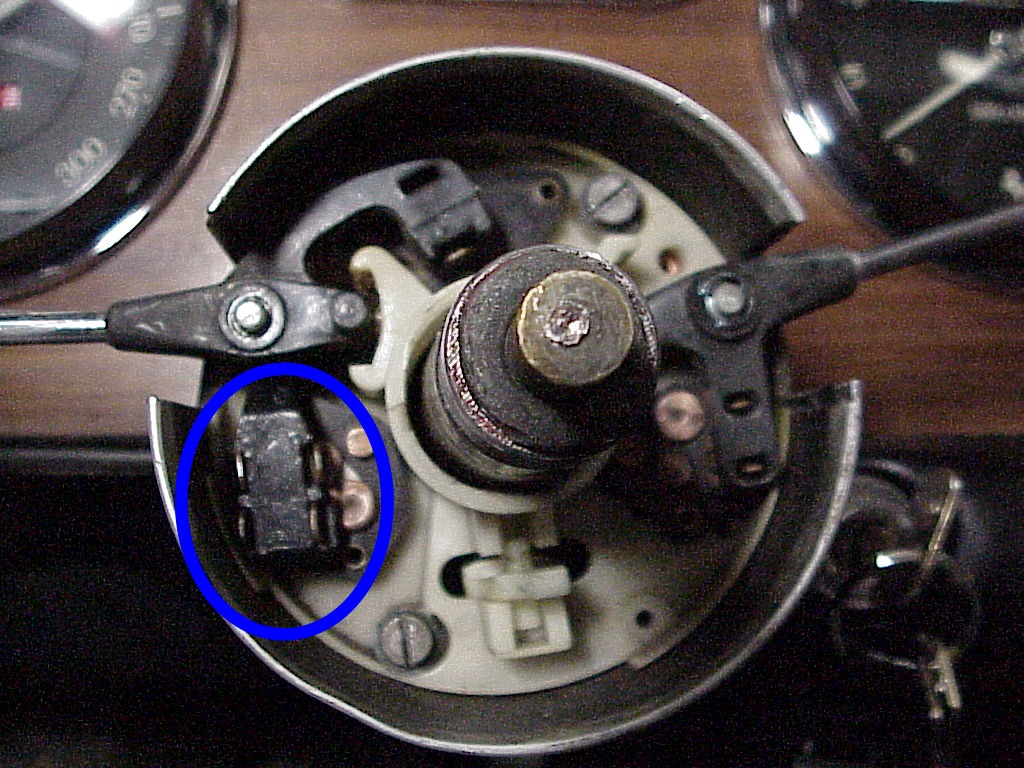
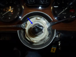
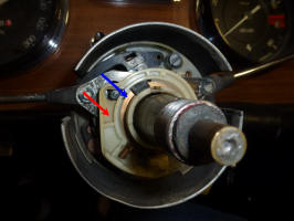
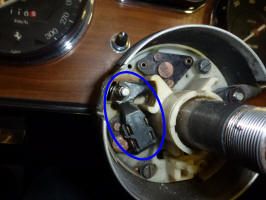
It was obvious when I got things apart. That U-shaped contact and spring were loose at the bottom of the switch area. I removed the two switches on the left (turn and headlight) and looked at the headlight stalk. The arm (see blue oval below) of the switch was raised off the switch contacts considerably. I don't know if this was from the initial mold of the part or the plastic has just deformed over the years. I thought about this for a while and finally decided that I would try and reform it using a heat gun. Since the material was a thermo-plastic, it did get soft and pliable after a few seconds of heat. I was able to make the arm parallel again. However, it took about 5 tries to get the exact angle necessary for all of the switches to work properly. I also shortened the switch springs down to 7/16" to lessen the pressure on the end of the arm.
It was a good opportunity to polish the steering wheel and associated parts for the concours since everything was apart.
I also noticed that the high and low beam lights were turned on at the incorrect switch positions. Since the wires to the headlight buckets were correct, I just took out the headlights and swapped the wires going to each bulb. Now the upper switch position is parking lights, center is low beam and lower is high beam.
I thought that I had this problem completed fixed. However one night after the headlights had been on for an hour or so, the low beams stopped working. Luckily I was just a few blocks from home, so I switched to the high beams which did still work. After thinking about this for a few weeks (I seldom drive the 330 at night), I figured out what has kept happening. There are no relays for the headlight circuit, so all of the current goes through those U-shaped contacts. The headlight bulbs are 50/45 watt, so on high beams the pair are drawing about 9 amps. The contacts get hot producing the same result on the arm as the heat gun. The arm gets pliable and the springs for the contacts bend it up. Eventually the contact no longer makes the connection and your headlights go out.
I had thought of just aligning the arm again and adding a pair of relays to carry the current. Then the U-shaped contacts would not heat up, never to cause a problem again. In the meantime, I saw a thread on FerrariChat about an individual that was molding new ends on 308 stalks and recently had to do one for a 330 GTC. The picture of the GTC stalk looked identical to mine, so I contacted him. After some email interchanges discussing the thermoplastic that had been used on mine and what he uses, I decided to have him put a new end on my stalk instead of using relays.
I had been planning on removing the dash in order to fix the A/C evaporator. I figured that it was a good time to pull the steering wheel and remove the stalk. That way the steering wheel would be out of the way of the dash removal and I would have time to send the stalk off and get it fixed while working on the A/C evaporator.
During this process, I had the bay door open for some more light. As I was down at the far end using the heat gun, I heard the tiny tut-tut that a hummingbird makes. I've had a couple of hummers fly in before so I went looking up at each skylight.
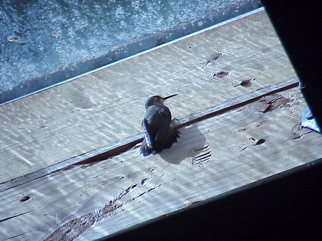
To get them out, I use a long hook that my Dad had in the hardware store used to get the V-belts that were hung on hooks high up on the wall. Hummingbirds are not very fearful, so I just put the hook up near it and after a few flights, it will land on the hook just like it is a branch. Then a careful lowering and tipping it towards the open door did the trick. As soon as it was outside of the door by a foot, it took off with never a thank you.
I'll update this once Verell has fixed my stalk and everything works OK.
Verell talked to the guy who made my stalk end originally. The material that was used has a heat deformation temperature (HDF) of only 150°F. The material that Verell will use has a HDF of 250°F (under heavy load), much higher. Verell is getting another part cast from the original mold so he can see exactly what mine looked like before all of the heat deformation occurred. He'll make a new mold from that part and then put a high temperature end on my stalk. So this should solve my headlight switch problem for good.
I got my stalk back from Verell with the new end. In addition, he included some lubricant with a high amount of copper in it. He had cleaned the U-shaped contacts and I cleaned the ones in the car in addition to lubricating them once it was assembled.
.JPG) |
.JPG) |
When I went to put the plate that holds the stalks in place, I found out a couple of things. One, the thickness of the new stalk end prevented me from putting on the plate that goes under the E-ring. I ended up thinning the stalk by about .075". Here you can see the extra space in the right picture. I reported this to Verell and I'm sure that he'll make an adjustment to the mold.
.JPG) |
 |
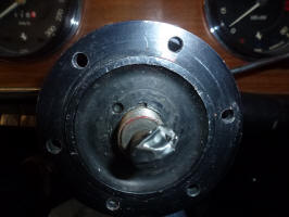
The second thing I learned was that the shaft that the stalks pivot on can be pushed down through its mounting thus effectively making it shorter. After I had thinned the stalk end, I came back and was confused as to why things wouldn't fit. At first I though that the spring loaded ball was keeping the stalks from fitting down as far as they had been when I did my original measurements. So I took everything apart again and noticed that the end of the shaft was lower. A quick pull by a pair of pliers restored its length and I was able to re-assemble everything properly.
Hopefully all of this will keep the heating under control and my headlights will continue to work after being on for a while. Once the dash is re-installed, I'll test the headlight circuits before I finish putting the steering column back together.
Verell makes a number of no longer available plastic parts including new ends for 308 stalks. Click here to contact Verell.
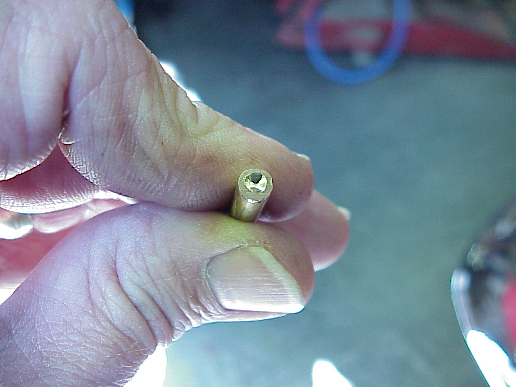
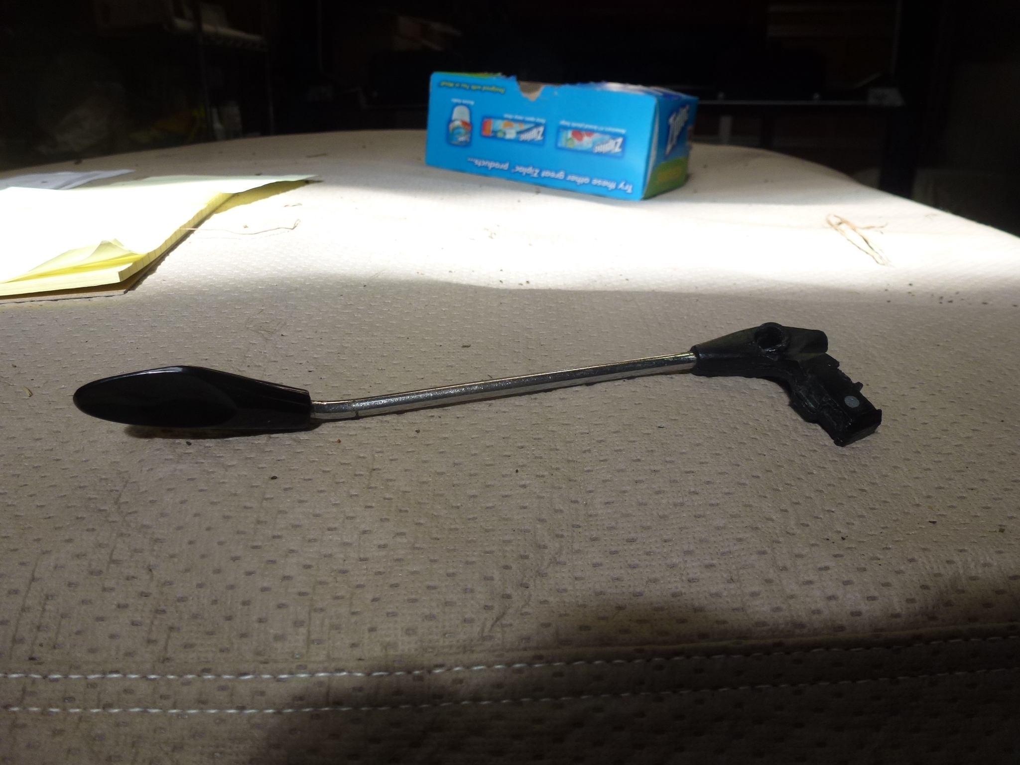
Well, the headlight stalk did last a number of years. However, when I was showing the car at a regional FCA concours, I managed to break it off.
This time, it broke off where the hole for the pivot shaft is. I mailed the broken stalk off the Verell to get a new end molded on.
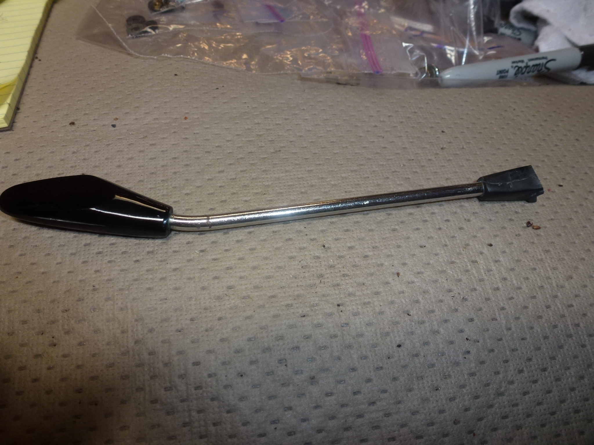
After a couple of weeks, the stalk came back with a new end.
This time, I'll detail all of the steps to remove and fix one of the stalks.
-
Disconnect the battery ground. This will prevent the horn from blowing as you work on the steering column.
-
Rotate the steering wheel so it is upside down. This puts the woodruff key slot so it is up and won't fall out.
-
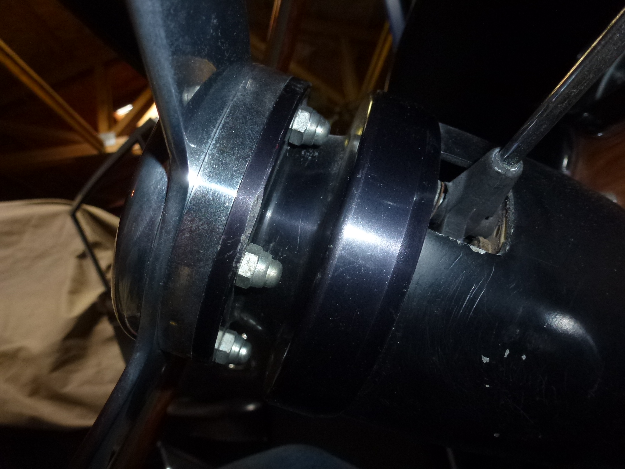
Take off the steering wheel. There are six acorn nuts under the hub that need to be removed.

-
Then the steering wheel, spacer, horn surround, horn button and spring come loose.
-
Remove the nut, washer and collar holding the hub to the steering column. There is a tabbed washer under the nut, so be sure to flatten any flanges bent up into the slots in the nut. You need a special socket that you can make.
-
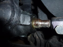
Remove the hub with a steering puller. I put a 13mm ½" socket over the horn contact for the screw of the puller to seat on.
-
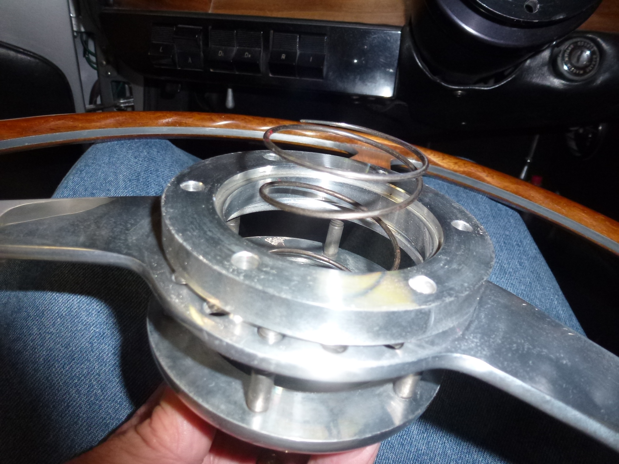
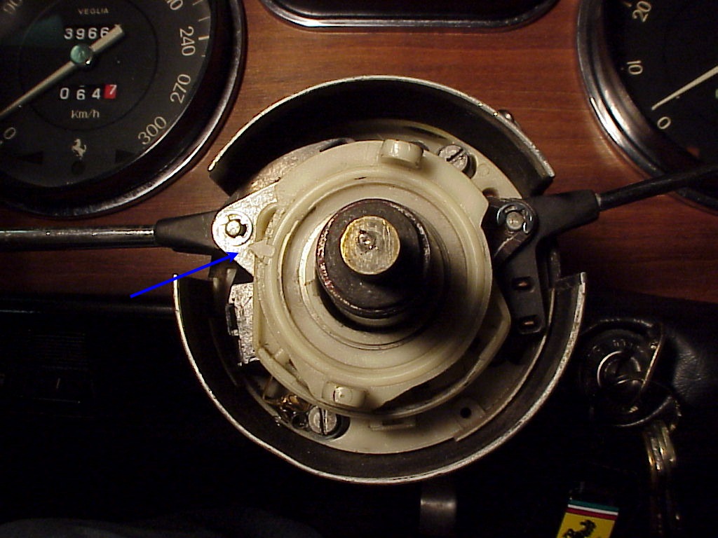
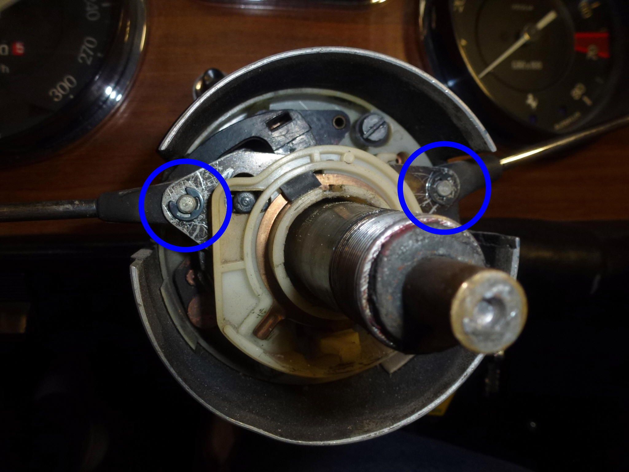
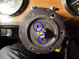
Now you are down to the complicated part. Remove the spring washer (see arrow) holding the plastic parts together.
-
Then pull off the plastic part that returns the turn signal lever to off after a turn. Note the location of the arrow so you can align it correctly later.
-
Remove the washer.

-
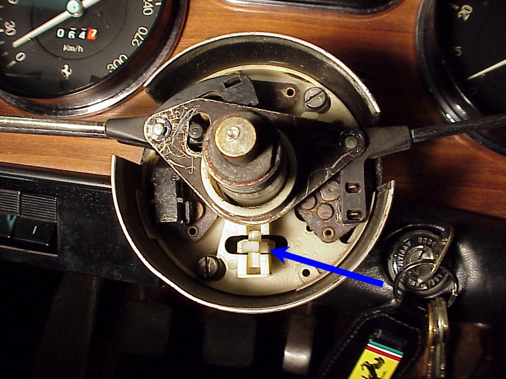
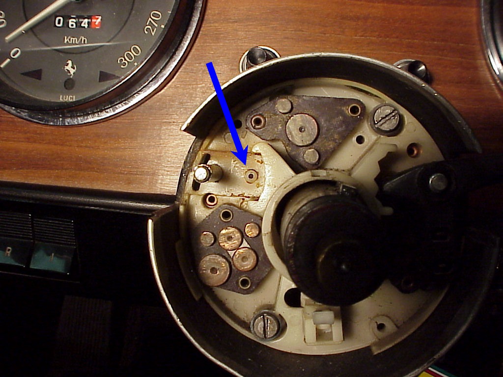
Now there is a copper ring (blue arrow) with a flange sticking down. This flange has a hole in it that has a spring loaded plastic piece sticking through it. The ring sits in a plastic mount (red arrow). Carefully pull the mount and ring off. The spring loaded piece will pull out, releasing the copper flange so the ring and mount come off.
-
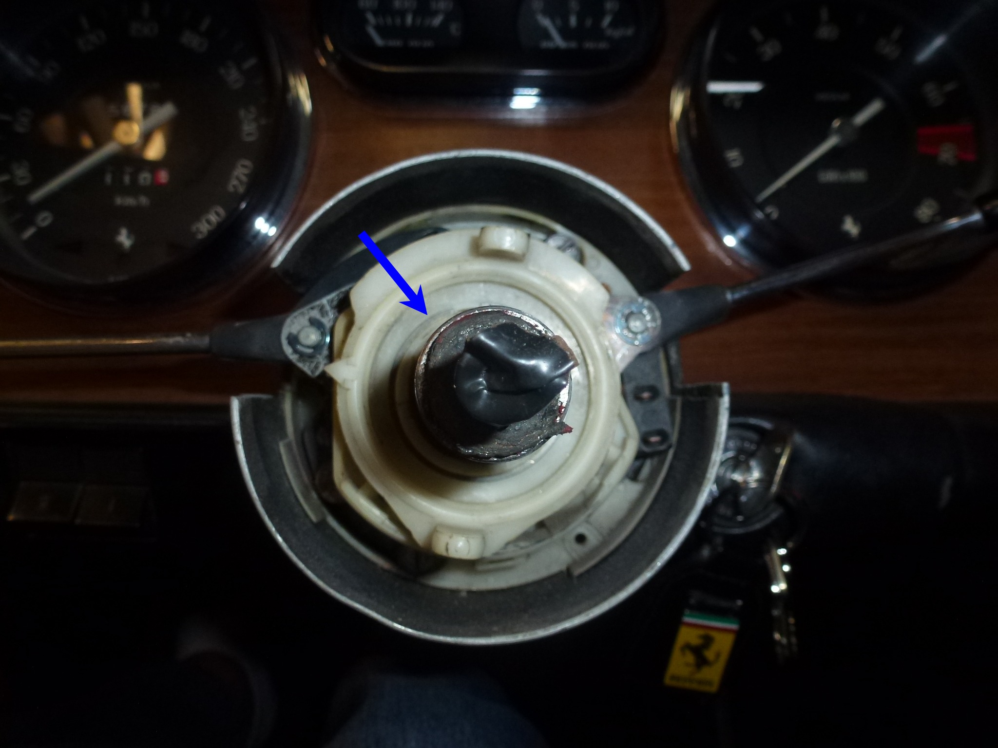
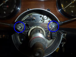
Now that everything is out of the way, we can start on the actual stalk area. Remove the E-clips (circled) holding the retaining plate. I use a stick magnet when removing clips like these so they don't fly off and disappear.
-
Remove the retaining plate and put the E-clip back on the shaft that you are not working on. It is easy to bump the opposite side stalk and have everything go flying. Don't ask how I know this.
-
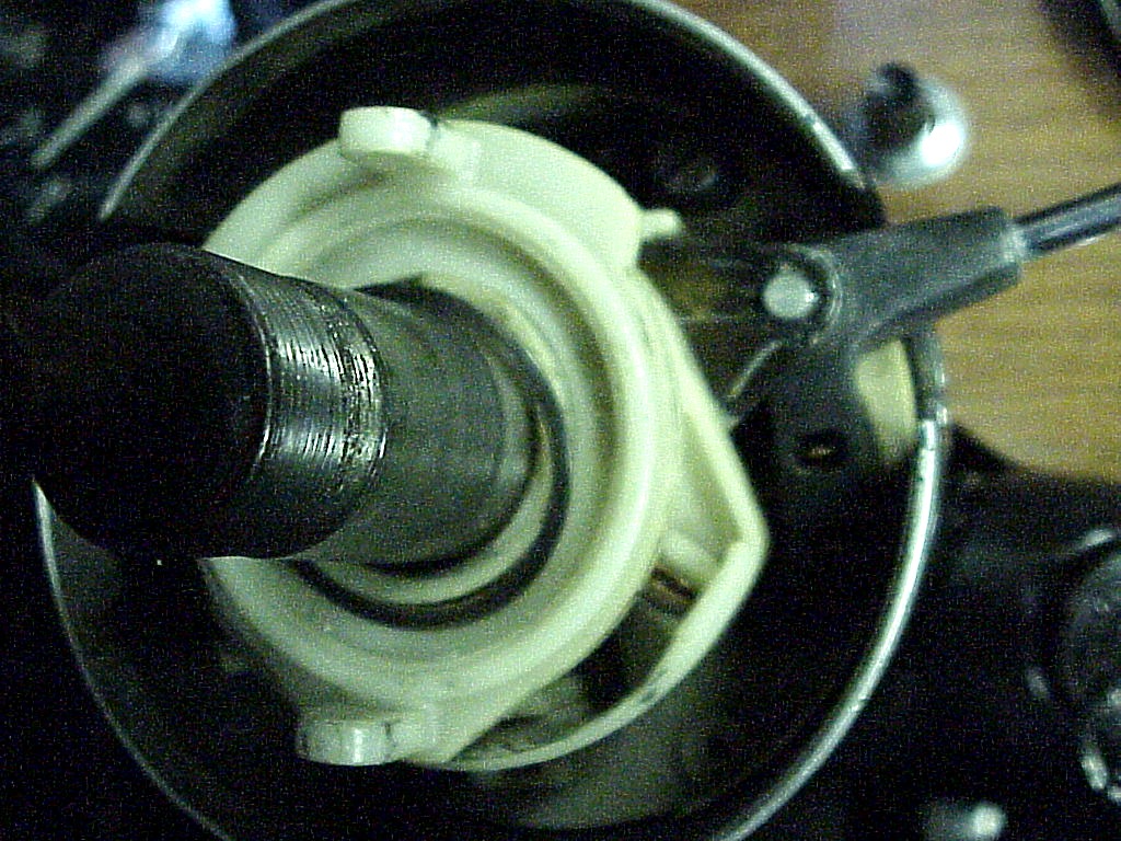
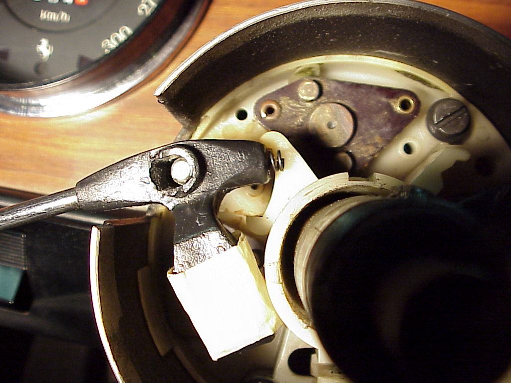
Remove the turn signal stalk. Note the stick magnet in place catching the ball and spring that is in the end of the stalk. If you rotate the stalk the same time as you pull up, the stalk comes up easier when the ball is no longer in a detent. There is also a spring loaded U-shaped electrical contact (red arrow) that wants to come off, so don't lose it or the spring. The second picture show the contacts on the headlight stalk.
-
Remove the headlight stalk in the same manner. This is what broke off.
-
Now the re-assembly. It is just the opposite, but with a couple of tricks I've figured out.
-
When putting each stalk back together, I use some tape to hold the springs and contacts in place. I cover over the sticky part on the contacts and side so the tape is only stuck to the top side. This makes removing of the tape much easier after the stalk in in place.
-
I use a special tool I made to position the ball so it depresses the spring at the end of the stalk as I'm sliding the stalk down the shaft.

-
Note that the shafts can slide down, so if the retainer plate and E-clips don't want to fit on, pull the shaft up with a pair of pliers.
-
Once the retainer plate and clips are in place, test everything:
-
Headlight operation, parking, low beam, high beam and flash.
-
Turn signals, both left and right.
-
Windshield wipers and washer (for 5 speed cars).
-
-
Getting the copper ring and hole in the flange back onto the pin from the spring loaded plastic part is fussy, but it can be done without removing the plastic part. I find a pair of forceps to grasp the plastic part useful to maneuver everything at the same time. These are the parts that return the turn signal to the off position.
-
Be sure and position the arrow on the turn signal return piece correctly.
-
The hub has two slots on the back side that fit over the the turn signal piece projections. If these aren't aligned, the turn signal won't automatically turn off after a turn.
-
Before the hub nut is installed, test that the turn signal lever returns to the off position correctly when the steering wheel is turned back to center.
-
The hub has a couple of indents in it. These are for the bottom tabs on the tabbed washer that goes under the steering column nut.
-
Now is the time to refinish the steering wheel if needed. Also polish the aluminum spokes (being careful of the engraving), spacer and horn button surround. You can also polish the horn button to remove any scratches in the plastic.
-
Turn the steering column to straight ahead. Position the wheels straight and turn as needed to align the steering column mark with the steering box mark. Then install the steering wheel so the spokes are down and at the 2 and 10 o'clock positions.
Finally, everything is back together and I don't have to drive around with the headlights on high beam.
-